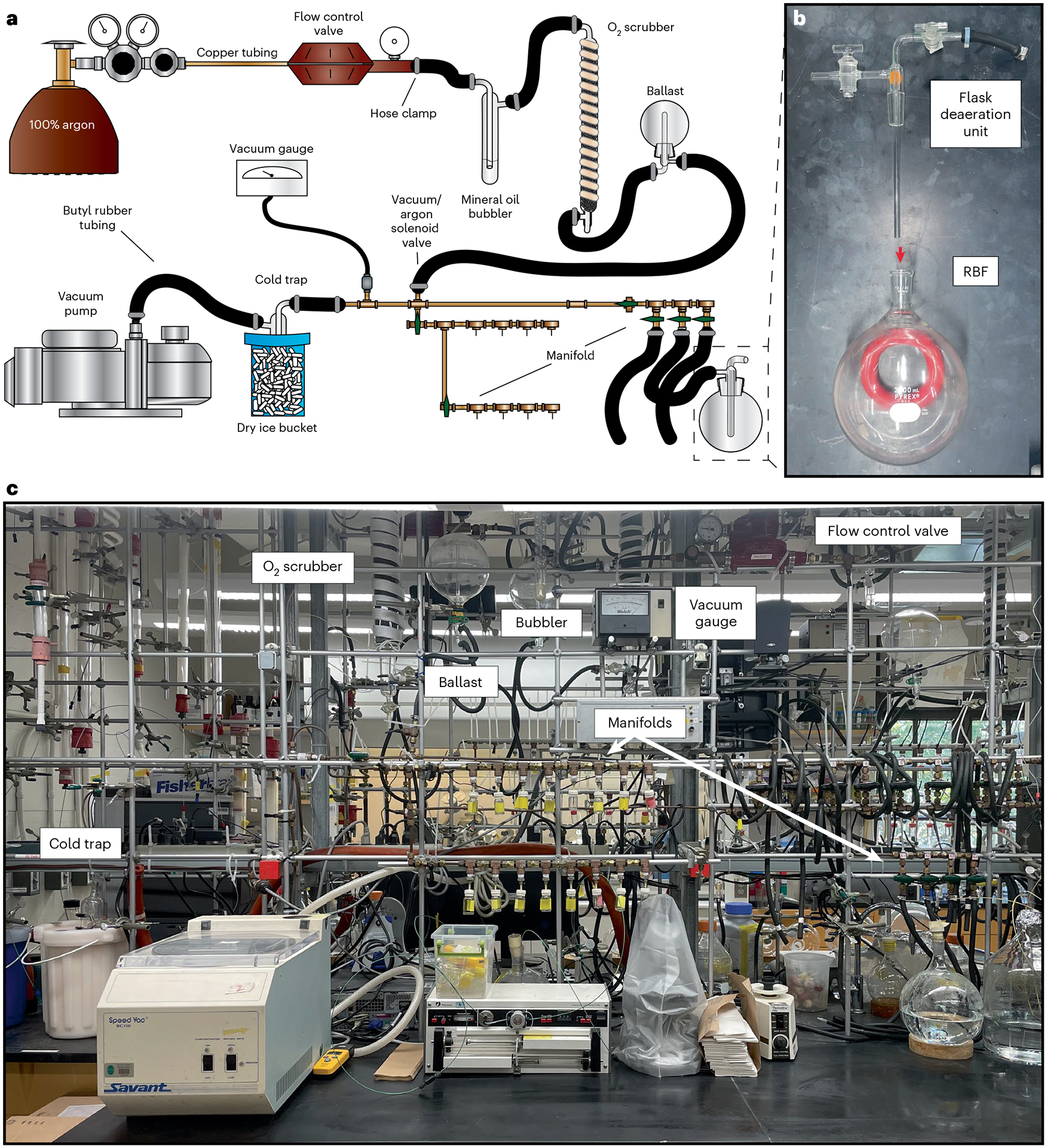
Fig. 2 |. Custom vacuum-manifold setup.

a, A schematic diagram of custom-built Schlenk line generally following flow of argon in a clockwise manner starting from the argon tank. b, Assembly of the flask deaeration unit within the RBF attached to the Schlenk line for degassing. c, Image of the depicted custom-built Schlenk line.
