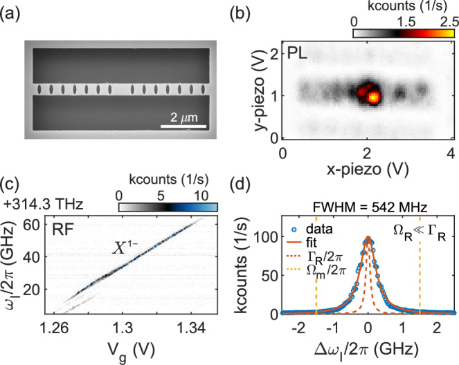
Fig. 2. Quantum dot characterisation.

a Scanning electron-microscope image of the fabricated device with seven shield elements on each side. b Photoluminescence (PL) map showing several QDs in the centre of the phononic-crystal beam. c Resonance fluorescence (RF) charge-plateau scan of the negative trion (X1−) of a QD close to the resonator’s centre. d Low-power frequency scan to determine the inhomogeneously-broadened linewidth, Γinh/2π = 550 MHz. The data are fitted to a Lorentzian. The transform limit (ΓR/2π) and the sideband position (Δωl = ± Ωm) are shown.
