

Abstract
MoS2 is regarded as one of the most promising potassium-ion battery (PIB) anodes. Despite the great progress to enhance its electrochemical performance, understanding of the electrochemical mechanism to store K-ions in MoS2 remains unclear. This work reports that the K storage process in MoS2 follows a complex reaction pathway involving the conversion reactions of Mo and S, showing both cationic redox activity of Mo and anionic redox activity of S. The presence of dual redox activity, characterized in-depth through synchrotron X-ray absorption, X-ray photoelectron, Raman, and UV–vis spectroscopies, reveals that the irreversible Mo oxidation during the depotassiation process directs the reaction pathway toward S oxidation, which leads to the occurrence of K–S electrochemistry in the (de)potassiation process. Moreover, the dual reaction pathway can be adjusted by controlling the discharge depth at different cycling stages of MoS2, realizing a long-term stable cycle life of MoS2 as a PIB anode.
Two-dimensional transition metal dichalcogenides (2D TMDs) are fundamentally fascinating and chemically versatile materials for a variety of applications.1,2 Among various TMDs, molybdenum disulfide (MoS2) has been investigated as a promising electrode material for potassium-ion batteries (PIBs) because the wide interlayer spacing (0.62 nm) and weak van der Waals interaction between the S–Mo–S slabs can effectively accommodate large K ions and lower the energy barrier of K-ion diffusion. A great deal of research attention has been directed toward increasing the PIB capacity of MoS2 by addressing issues such as poor electronic conductivity and structural instability through carbon coating3−5 and phase engineering (1T phase and 1T/2H mixed phase).6,7 Structural stability can be strengthened by expanding interlayer spacing8−10 and tuning the morphology and/or dimensionality of MoS2 to relieve the strain in vertical and radial directions during K-ion insertion.11,12 However, understanding of the electrochemical mechanism to store K-ions has not been progressed to the same extent as capacity enhancement due to the complexity in phase transition and kinetic processes involved in electrochemical K storage in MoS2.11,13−15
Electrochemical storage mechanism of alkali-ions in MoS2 is strongly affected by the thermodynamic formation energy and polarity of the alkali–metal–sulfur bond. The decomposition enthalpies of AMoS2 (A = Li, Na, K) into Mo and A2S are −4.46, −3.16, and −3.30 eV f.u.–1 for Li, Na, and K, respectively,16 indicating the thermodynamic driving force for the conversion reaction to occur decreases from Li to K. Kinetically, bond polarity decreases from the Li–S to K–S bond, which suggests the conversion reaction in the K-MoS2 system is more suppressed than the Li-MoS2 system. This could result in different mechanisms between K and Li storage in MoS2. Even comparing Li and Na storage in MoS2, the mechanisms reported in the literature varied from study to study, and diverse conclusions were drawn. It has been reported that MoS2 was regenerated after delithiation, accompanied by the structural transition from bulk to nanostructures.17 However, the regeneration was not observed in some other studies where partially reversible conversion reaction back to MoS218 and even irreversible conversion reaction19 were observed. Sodiation in MoS2 was reported to be a reversible16,20 and an irreversible21 conversion process with the structure changing to few layers. Another study22 reported MoS2 failed to undergo conversion reaction; instead, sodiation caused structural transition forming distorted MoSx clusters, with partial regeneration to MoS2 after desodiation. There have been very limited studies on K storage in MoS2, but vastly different results were seen. Du et al. reported K-ion favored intercalating in MoS2 to form KMoS2, and the reversible reaction between KMoS2 and KxMoS2 was limited only to an intercalation process, which is responsible for K storage.23 However, other studies reported a range of discharge products including K2S24 and a mixture of KxMoS2, K2S5, and K2S,25,26 suggesting that K-ion storage in MoS2 might undergo a more complex mechanism than the Li and Na counterparts.22,23,27,28 Note that the kinetics of K-ion diffusion in MoS2 is sluggish due to the large size of the K ion, and this can further increase the complexity of the K-ion storage mechanism.
In this work, we investigated the mechanism of the K storage process in MoS2 using commercially available material and a combination of electrochemical, spectroscopic, structural, and morphological characterizations. We revealed the formation of metallic Mo and molecular S at the depotassiated state of MoS2, which is due to the irreversible oxidation of the metallic Mo formed at the potassiated state to Mo4+ and the resulting oxidation of S2– to S0. As a result, a dual reaction pathway consisting of Mo cationic redox activity and S anionic redox activity (i.e., K–S electrochemistry) directed the K storage process in MoS2. Moreover, we provided a solution for controlling discharge depth at different cycling stages to realize high cycling stability and rate capability. Unlike the mainstream study of MoS2 for PIBs, our investigation reveals interesting simultaneous cationic and anionic redox activity, contributing new insights into design strategies to further enhance the PIB performance of MoS2.
Phase purity and chemical composition of commercial MoS2 were confirmed by the results of X-ray diffraction (XRD, Figure S1a), Raman (Figure S1b), and X-ray photoelectron spectroscopy (XPS, Figure S1c,d). It shows a sheet-like morphology with an average lateral size of ∼30 μm (Figure S1e,f) and an interlayer spacing of 0.62 nm (inset in Figure S1e), with Mo and S homogeneously distributing across the sheets (Figure S2). We first investigated the galvanostatic charge/discharge (GCD) profiles of the MoS2 electrodes cycled in the range of 0.001 to 2.5 V (denoted as Route A in Figure 1a) in the half-cell configuration, as this has been the voltage range (i.e., deep discharge) used in the literature to study MoS2 as an anode material of PIBs.29−32 Shown in Figure S3a, the first discharge curve exhibited three voltage plateaus, suggesting a multistep potassiation process. XRD patterns (Figure S3b) were obtained for the discharge products at various stages indicated in Figure S3a. At stage II, the (002) peak was broadened and a new peak at 8.9° appeared, which indicates that the initial K-ion intercalation retains the layered structure but expands the interlayer spacing.33 Further discharging to stage III caused more K-ion intercalation, as evidenced by the increase in peak intensity at 8.9° and the near disappearance of the original (002) peak. From stage III to IV, a long and stable voltage plateau appeared at ∼0.1 V and both peaks at 14.3° and 8.9° diminished, while a broad peak appeared at 13.4°. This indicates that the layered structure was destroyed and amorphous products formed at the deep discharge condition. At the end of the following charge (stage V), no crystalline product(s) can be detected, suggesting that there was minimal to no restoration of the pristine layered structure. The observations of the GCD profiles via Route A (0.001–2.5 V) directed our attention to the control of discharge depth and its effect on K storage mechanism in MoS2. Since the layered structure was retained at >0.2 V potassiation and amorphous discharge products were formed at <0.2 V potassiation, we kept the discharge depth at 0.001 V in the first cycle but changed it to 0.2 V from the second cycle and onward (denoted as Route B: 0.001–2.5 V in the first cycle and 0.2–2.5 V from the second cycle in Figure 1b). Figure 1b shows the GCD profiles via Route B and the XRD patterns of the MoS2 electrodes at various stages of the cycles shown in Figure S4. The GCD profiles share similarities with those via Route A, including the three defined plateau regions in the first discharge curve and the sloping curves in the following cycles. The similarities can also be seen from the CV curves via the two routes (Figure S5), showing similar voltages of the reduction and oxidation peaks. No crystalline phase(s) was recovered via Route B and (de)potassiation product(s) remained amorphous judging from the XRD patterns.
Figure 1.

GCD profiles of MoS2 via (a) Route A and (b) Route B. Comparison of (c) rate capability and cycle stability at (d) 100 mA g–1 and (e) 1 A g–1 of MoS2 cycled via the two routes.
However, we found that the two routes resulted in a surprisingly different cell performance. First, cycle1 charge and cycle2 discharge capacities via route B were 393 and 273 mAh g–1, respectively, at 20 mA g–1, being close to the corresponding capacity via route A (318 and 279 mAh g–1). It is not difficult to understand cycle1 charge capacity being close, as the two routes underwent the same deep discharge process during the first cycle. However, the similar cycle2 discharge capacity suggests there was extra capacity generated in the 0.2–2.5 V range via Route B to compensate for the capacity loss that would have been gained in the 0.001–0.2 V range via Route A. Second, despite the smaller voltage range from cycle 2 onward, Route B resulted in higher capacities than Route A across all current densities tested for rate capability (Figure 1c). The cell via Route B delivered capacities of 256, 236, 222, 198, 160, 134, 124, and 91 mAh g–1 at 30, 50, 100, 200, 500, 800, 1000, and 2000 mA g–1, respectively. It retained 263 mAh g–1 when returning to 30 mA g–1. In contrast, the cell via Route A showed rapid capacity decay and failed at >1 A g–1. Third, Route B exhibited much better cycling stability than Route A (Figure 1d). At 100 mA g–1, the cell via Route B delivered an initial discharge capacity of 167 mAh g–1, 77% of which was retained after 200 cycles. Although the cell via Route A delivered a higher capacity in the initial cycles due to the wider voltage range (0.001–2.5 V), only 54% capacity was retained after 200 cycles, being surpassed by the cell via Route B from cycle154 onward. The same trend was observed at 1 A g–1 over 500 cycles (Figure 1e). Route B resulted in 84% capacity retention in comparison to 44% retention via Route A. Fourth, Route B showed a higher Coulombic efficiency (CE) than Route A (Figure 1d). The initial CE of the two routes is ∼65% due to the same discharge depth at 0.001 V. But CE varies in the next few cycles between the two routes, as the discharge depth was different from the second cycle onward. The CE stabilized at ∼99% after 6 cycles for Route A, whereas it reached >99% within 3 cycles for Route B. We are mindful that the PIB performance obtained here is not comparable to some of the best in literature obtained by forming nanocomposites15,34 because commercial MoS2 in a bulky size was directly used in our work. However, the comparison of the two routes shown here is intriguing because despite the smaller voltage range of Route B than Route A from cycle 2 onward, the former exhibited better rate capability, more stable cycle life, and high capacity over long-term cycling. This indicates that K storage in MoS2 may undergo a more complex process than what has been reported in literature, i.e., an intercalation reaction followed by a conversion reaction (possible overlap depending on sample status). Additional reaction(s) may occur simultaneously, and controlling the discharge depth can affect the additional reaction(s), thus affecting the PIB performance of MoS2.
We then turned our focus to investigating the change of Mo and S, the two elements in MoS2, during the cycles. We combined various spectroscopy techniques including X-ray absorption (XAS), XPS, Raman and UV–vis spectroscopies for the investigation due to the amorphous nature of the discharge and charge products as shown in the previous discussion. The local structural change of the Mo species in MoS2 in the first two cycles via Route B was characterized using EXAFS spectra (Figure 2a).35Figure 2a shows the Fourier transformed (FT) Mo K-edge EXAFS taken at various states during the first two cycles via Route B. The fitting of the EXAFS spectra is shown in Figure S6. Two strong peaks can be seen at 2.4 and 3.1 Å from pristine MoS2, representing the Mo–S interaction in the first coordination shell and the Mo–Mo interaction in second coordination shell of 2H-MoS2, respectively (Figure 2a).36 When discharged to 0.2 V, the Mo–Mo (3.1 Å) peak of MoS2 decreased, and the decrease in intensity was caused by structural transformation of MoS2 to KxMoS2.18 Further potassiation to 0.001 V caused a significant decline in the amplitude of the Mo–S peak and a strong amplitude of the Mo–Mo interaction at 2.8 Å, the latter corresponding to metallic Mo seen in the Mo foil reference. This proves the occurrence of the conversion reaction that results in the loss of layered structure and the reduction of Mo4+ to Mo0.18 This is also confirmed from the best-fit results of the coordination number (CN) provided in Table S1. The CN of Mo–S bond when discharged to 0.2 V was close to the CN at the pristine state (5.7 vs 5.9). Further discharging to 0.001 V caused a decrease in CN to 2.9, signaling that ∼50% of the phase fraction of MoS2 is converted to Mo metal. At the end of the first charge, Mo–S peak was resumed due to the restoration of the MoS2 structure upon depotassiation, but not to the same extent of pristine state. Interestingly, the Mo–Mo peak was present alongside the Mo–S peak with a similar amplitude, which clearly suggests the partial oxidation of Mo0 back to Mo4+ and the coexistence of metallic Mo with the restored MoS2. Mo–S CN restored to 5.9, and Mo–Mo metal CN reduced to 1.9 (Table S1). The next cycle in the 0.2–2.5 V range showed reversible peak changes, where Mo–S decreased upon potassiation and increased upon depotassiation, whereas Mo–Mo was present throughout (de)potassiation and became even stronger than Mo–S after second depotassiation.
Figure 2.

(a) EXAFS spectra of MoS2 cycled via Route B during the 1st and 2nd discharge/charge process. Wavelet analysis of the Mo K-edge EXAFS of MoS2 cycled via Route B at (b) the 1st discharged state, (c) the 1st charged state, (d) the 2nd discharged state, and (e) the 2nd charged state. (f) Mo 3d XPS spectra of MoS2 cycled via Route B in the charged states. (g) TEM image of MoS2 cycled via Route B at the charged state (inset: SAED pattern).
The wavelet transform analysis from EXAFS results was performed to further understand this process (Figures 2b–e and S7). The intensity maximum associated with the Mo–S coordination at 5.5 Å–1 decreased upon potassiation to 0.2 V (1st discharge 0.2 V, Figure S7c) compared to pristine MoS2 (Figure S7a). Further potassiation to 0.001 V (1st discharge of 0.001 V, Figure 2b) caused a significant decrease in the same coordination. But the intensity maximum occurred at 6.1 Å–1 with the bond distance of 2.6 Å which corresponds to the Mo–Mo coordination of Mo metal (Figure S7b). Upon depotassiation (1st charge of 2.5 V, Figure 2c), the Mo–S coordination at 5.5 Å–1 was less intense compared to its pristine state, which implies partial restoration of MoS2. It is worth noting that less intensive metallic Mo–Mo coordination at 6.9 Å–1 coexists after depotassiation (1st charge 2.5 V), confirming the presence of Mo metal. In the second cycle, the change of the intensity corresponding to Mo–Mo metal coordination at 6.1 Å–1 at potassiation (2nd discharge 0.2 V, Figure 2d) and depotassiation (2nd charge 2.5 V, Figure 2e) can further confirm the existence of the Mo metal.
In addition, the presence of metallic Mo upon depotassiation was proven by Mo 3d XPS spectra. As shown in Figure 2f, the Mo0 peaks can be seen at 228.9 (3d3/2) and 226.1 eV (3d5/2) at the end of the first and second charge, together with Mo4+ from the reverse conversion reaction and Mo5+/6+ due to partial surface oxidation of the XPS samples. Furthermore, metallic Mo at the depotassiated state of MoS2 can be detected even after long-term cycles.37 As shown in Figures 2g and S8, dense particles with an average size of 1.5 nm were distributed throughout the MoS2 layers. The particles can be characterized as Mo nanocrystals from the selected area electron diffraction (SAED) pattern that shows diffraction spots indexed to the (011) planes of MoS2 (ICSD: 98–003–9095) and the (011) and (002) planes of Mo (ICSD: 98–005–1508), confirming the coexistence of MoS2 and Mo in the charged state after cycling. In the case of Route A, we also observed the coexistence of metallic Mo0 and Mo4+ upon depotassiation (Figure S9). Based on these results, it is safe to say that the reverse conversion from Mo0 to Mo4+ during depotassiation was incomplete, and metallic Mo was present throughout the cycles. However, the consistent presence of metallic Mo would reduce the electrochemically active species in the electrode, and thus, there must be other species that are electrochemically active to contribute to the capacity. This prompted us to investigate the change of S.
Figure 3 shows the change of the S species in MoS2 in the first 2 cycles via Route B. The S 2p XPS spectra in the first cycle are shown in Figure 3a. It shows various potassium polysulfides at the discharged state (potassiation), which agrees with previous work.38,39 Particularly, the presence of S2–, evidenced by the peaks at 160.1 and 158.7 eV, signals the formation of K2S and the reduction of Mo4+.38 What is interesting is that, after depotassiation, peaks of S0 appeared at 163.2 and 164.8 eV,40,41 and the peak area of S32–/Sx2– increased at the expense of the decrease in S22–/S2. The same changes of the S species were observed in the second cycle (Figure 3b) but with a stronger S0 peak intensity. This suggests that during depotassiation, S species was oxidized alongside the partial oxidation of metallic Mo, leading to the formation of S0 after charge, which essentially contributes to electron transfer and thus capacity. To ascertain our results, we tested the Raman spectra of the MoS2 electrodes at charged states (depotassiation) in the first and second cycles. As shown in Figure 3c, compared with pristine MoS2, the signature E12g and A1g vibrational modes largely diminished, signaling the partial restoration of pristine MoS2. New peaks evolved at 155 and 244 cm–1 in both cycles, corresponding to the torsion and bending vibration modes of sulfur (S8)42 and therefore further proving the formation of S0 after depotassiation. Our analysis of the S species in MoS2 points to the fact that, beside Mo, S was electrochemically active after the first potassiation and participated in the oxidation and reduction reactions in the following cycles, effectively making K–S chemistry a part of the K storage mechanism in MoS2; in another word, the mechanism is based on both Mo cationic redox and S anionic redox activities. As known, the S conversion process involved in K–S chemistry can lead to the formation of both low-order polysulfides and high-order polysulfides, the latter of which are in the liquid form and can dissolve in electrolytes.43,44 If K–S chemistry takes part in the K storage in MoS2, we should see high-order polysulfides formed during potassiation dissolving in the electrolyte; as expected, we detected the absorption peaks of S62– and S52– at 300 and 318 nm,41,43 respectively, in the UV–vis absorption spectrum of the electrolyte extracted from the separator after the second discharge (Figure 3d). In the case of Route A, since the discharge depth was kept at 0.001 V in all cycles, it is expected that Mo cationic redox and S anionic redox should both contribute to K storage, and the extent to which S anionic redox contributes should be higher than Route B, because deeper discharge depth (0.001 vs 0.2 V) could promote more Mo reduction and as a result, more irreversible Mo oxidation and more S oxidation. As shown in Figure S10, S0 was observed after the first and second charge in the XPS (Figure S10a,b) and Raman spectra (Figure S10c), with more noticeable signals after the second charge compared to Route B. Also, S62– and S52– absorption peaks were observed in the UV–vis absorption spectrum (Figure S10d).
Figure 3.
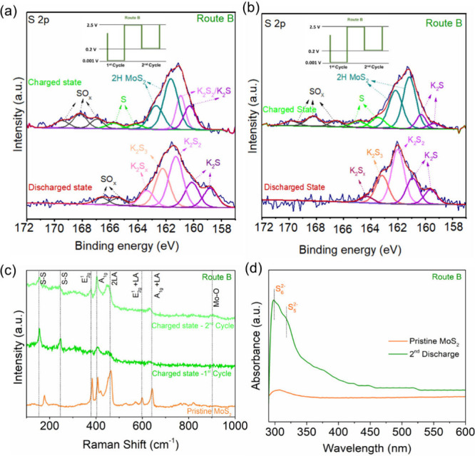
S 2p XPS spectra of MoS2 via Route B in the (a) 1st and (b) 2nd cycles. (c) Raman spectra of MoS2 cycled via Route B in the charged states. (d) UV–vis absorption spectra of the electrolyte cycled via Route B in the discharged state of MoS2.
Our next characterization was to show the cationic and anionic dual redox activity can be sustained over repeated cycles for the K storage in MoS2. As shown in Figure S11a, high-order polysulfides S62– and S52– were observed at 245 and 297 nm, respectively, in the UV–vis absorption spectrum after 20 cycles for both Route A and Route B. In the Raman spectra shown in Figure S11b, the presence of the torsion and bending vibration modes of S0 proves the reversible transformation of polysulfides to sulfur at the charged state for both routes. Upon combing the HRTEM results shown in Figure 2g, where Mo0 was detected at the charged state, the collective results demonstrate the active cationic and anionic dual redox reactions can sustain over repeated cycles, forming dual reaction pathways of the K storage in MoS2.
Furthermore, we pointed out in the previous discussion that multiple reactions may occur during K storage in MoS2 and controlling the discharge depth could affect the reactions and thus the PIB performance of MoS2. Building on our results of cationic and anionic dual redox activity, we carried out postcycling morphological and structural characterizations to understand how controlling discharge depth, the main difference between Route A and Route B, affects the dual reaction pathways and the resulting performance. Constant cycling in the 0.001–2.5 V range (Route A) can maximize capacity because it maximizes the conversion reaction of the Mo species, i.e., cationic redox activity, and potentially maximizes the formation of S0, i.e., anionic activity, due to the increasingly irreversible Mo oxidation. This was reflected by the high capacity shown in Figure 1. However, this could result in three consequences: (i) repeatedly destroying the MoS2 layered structure at deep discharge depth and reconstructing the structure during charge, (ii) accumulating irreversible discharge products, and (iii) increasing the S0 formation and polysulfide dissolution in the electrolyte, all of which are responsible for the capacity decay and deteriorated rate capability via Route A. SEM images (Figures 4a and S12a) show large agglomerations and cracks formed after 1000 cycles, signaling a much thicker (presumably due to continuous formation of solid-electrolyte interphase (SEI)) and stiff surface of the electrode. TEM image (Figure 4b) shows the total collapse of the pristine layered structure (Figure S1e), likely increasing K-ion interparticle diffusion resistance. In contrast, discharging to 0.001 V in cycle1 and raising the discharge depth to 0.2 V from cycle2 (Route B) can balance between maximizing dual cationic and anionic redox activity and minimizing surface deterioration and structural collapse because the dual redox activity is activated in cycle1 and at the same time, the MoS2 structure is less prone to collapse from cycle2 after the extent to which the conversion reaction takes place is reduced. The electrode was removed after 1000 cycles. Figures 4c and S12b show a much smoother surface with more defined texture and without cracks via Route B compared to Route A. Layered structure was retained with expanded interlayer spacings (Figure 4d). Additionally, metallic Mo nanoclusters might act as active sites to bind polysulfides and hinder the shuttle effect.19,45−48 Collectively, these contributing factors enable long-term cycling stability and rate capability via Route B. Therefore, utilizing cationic and anionic dual redox activity can be advantageous for storing K in MoS2, but its execution needs to be balanced.
Figure 4.
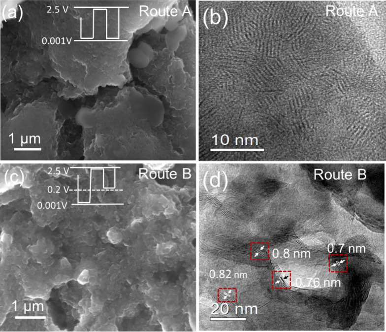
(a, c) SEM and (b, d) TEM images of the MoS2 electrodes cycled via (a, b) Route A and (c, d) Route B after 1000 cycles.
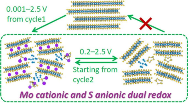
With the above results and discussion, we illustrate in Figure 5 the K storage mechanism in MoS2. The initial potassiation process at the discharge depth of 0.001 V undergoes a conversion reaction to form a mixture of discharged products, including metallic Mo nanoclusters, potassium (poly)sulfides, and potassium intercalated MoS2 (KxMoS2). The subsequent depotassiation process up to 2.5 V does not completely oxidize metallic Mo to higher oxidation states, and a part of metallic Mo remains, which results in a part of potassium sulfides being oxidized to S0. In the following cycles, a dual reaction pathway consisting of Mo cationic redox activity and S anionic redox activity takes place, enabling the capacity contribution from transition metal Mo and K–S battery chemistry. Via Route A with which the discharge depth is kept at 0.001 V, the MoS2 layered structure is destroyed over cycles and polysulfide dissolution in the electrolyte is increased, leading to fast capacity decay and unstable cyclability. Via Route B with which discharge depth is kept at 0.2 V from cycle 2 onward, severe MoS2 structural deterioration is avoided over cycles and polysulfide dissolution in the electrolyte is reduced, enabling stable performance without losing the dual cationic anionic redox reactivity.
Figure 5.
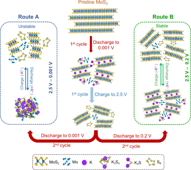
Schematic representation of the mechanism of the K-ion storage process in MoS2 via Routes A and B.
In summary, we carried out a mechanistic study on the K storage process in MoS2 and revealed that Mo and S conversion reactions occurred simultaneously during (de)potassiation. The process utilized the cationic redox activity of Mo and the anionic redox activity of S simultaneously, which, to the best of our knowledge, was reported for the first time regarding the use of MoS2 as an anode material for PIBs. Furthermore, we demonstrated the importance of controlling discharge depth in enabling the advantages of dual redox activity. A balance needs to be taken into consideration between maximizing the dual redox activity and minimizing the structural deterioration of MoS2 and the dissolution of polysulfides. To this end, we showed that it is beneficial to deep discharge to 0.001 V in the initial cycle and raise the discharge depth to 0.2 V from the second cycle onward, which enhances capacity retention, cycling stability, and rate capability compared to consistent deep discharge to 0.001 V. We believe our work provides fresh insights into electrochemically storing K-ions in transition metal chalcogenides and an unconventional approach to optimize their PIB performance.
Acknowledgments
Y.X. acknowledges the support of the Engineering and Physical Sciences Research Council (EP/V000152/1, EP/X000087/1), Leverhulme Trust (RPG-2021-138), and Royal Society (IEC\NSFC\223016). The authors also acknowledge the B18 beamline at Diamond Light Source (DLS) for the allocated experiment session (session ID SP30102-1). For the purpose of open access, the author has applied a Creative Commons Attribution (CC BY) license to any Author Accepted Manuscript version arising.
Supporting Information Available
The Supporting Information is available free of charge at https://pubs.acs.org/doi/10.1021/acsmaterialslett.4c01455.
Materials and methods, characterization of commercial MoS2, CV curves and XRD patterns at various stages of discharge/charge via the two routes, fitting of the EXAFS results and wavelet analysis of pristine MoS2, Mo foil and MoS2 discharged to 0.2 V via Route B, postcycling HRTEM image of MoS2 cycled via Route B, XPS/Raman/UV–vis results of MoS2 cycled via Route A in the 1st and 2nd cycles, postcycling Raman/UV–vis results and SEM images of MoS2 (PDF)
Author Contributions
CRediT: Ajay Piriya Vijaya Kumar Saroja conceptualization, data curation, formal analysis, methodology, visualization, writing - original draft, writing - review & editing; Yupei Han data curation, formal analysis, investigation, validation; Charlie Nason formal analysis, methodology, validation; Gopinathan Sankar data curation, formal analysis, investigation, methodology, validation, writing - review & editing; Yi Lu methodology; Henry Tinker visualization; Andrew A. Stewart data curation; Veronica Celorrio data curation, methodology; Min Zhou conceptualization; Jiayan Luo formal analysis; Yang Xu conceptualization, formal analysis, funding acquisition, investigation, project administration, resources, supervision, validation, visualization, writing - review & editing.
The authors declare no competing financial interest.
Special Issue
Published as part of ACS Materials Lettersspecial issue “Post-Lithium Battery Materials”.
Supplementary Material
References
- Chowdhury T.; Sadler E. C.; Kempa T. J. Progress and Prospects in Transition-Metal Dichalcogenide Research beyond 2D. Chem. Rev. 2020, 120 (22), 12563–12591. 10.1021/acs.chemrev.0c00505. [DOI] [PubMed] [Google Scholar]
- Chhowalla M.; Shin H. S.; Eda G.; Li L. J.; Loh K. P.; Zhang H. The Chemistry of Two-Dimensional Layered Transition Metal Dichalcogenide Nanosheets. Nat. Chem. 2013, 5 (4), 263–275. 10.1038/nchem.1589. [DOI] [PubMed] [Google Scholar]
- Teng Y.; Zhao H.; Zhang Z.; Li Z.; Xia Q.; Zhang Y.; Zhao L.; Du X.; Du Z.; Lv P.; et al. MoS2 Nanosheets Vertically Grown on Graphene Sheets for Lithium-Ion Battery Anodes. ACS Nano 2016, 10 (9), 8526–8535. 10.1021/acsnano.6b03683. [DOI] [PubMed] [Google Scholar]
- Chen L.; Chen Z.; Xiang T.; Wang X.; Feng S.; Yang S.; Wang Z.; Feng Z.; Li X.; Huang J. Expanded MoS2@C Nanosheets by Three-Roll Milling for High-Performance Potassium Ion Batteries. FlatChem. 2023, 40 (March), 100520. 10.1016/j.flatc.2023.100520. [DOI] [Google Scholar]
- Cai M.; Zhang H.; Zhang Y.; Xiao B.; Wang L.; Li M.; Wu Y.; Sa B.; Liao H.; Zhang L.; et al. Boosting the Potassium-Ion Storage Performance Enabled by Engineering of Hierarchical MoSSe Nanosheets Modified with Carbon on Porous Carbon Sphere. Sci. Bull. 2022, 67 (9), 933–945. 10.1016/j.scib.2022.02.007. [DOI] [PubMed] [Google Scholar]
- Yao K.; Xu Z.; Ma M.; Li J.; Lu F.; Huang J. Densified Metallic MoS2 Graphene Enabling Fast Potassium-Ion Storage with Superior Gravimetric and Volumetric Capacities. Adv. Funct. Mater. 2020, 30, 2001484–2001492. 10.1002/adfm.202001484. [DOI] [Google Scholar]
- Qin L.; Xiao N.; Zhang S.; Chen X.; Wu Y. From K-O2 to K-Air Batteries: Realizing Superoxide Batteries on the Basis of Dry Ambient Air. Angew. Chemie - Int. Ed. 2020, 59 (26), 10498–10501. 10.1002/anie.202003481. [DOI] [PubMed] [Google Scholar]
- Kang W.; Wang Y.; An C. Interlayer Engineering of MoS2nanosheets for High-Rate Potassium-Ion Storage. New J. Chem. 2020, 44 (47), 20659–20664. 10.1039/D0NJ04314A. [DOI] [Google Scholar]
- Zhang Y.; Zhu L.; Xu H.; Wu Q.; Duan H.; Chen B.; He H. Interlayer-Expanded MoS2 Enabled by Sandwiched Monolayer Carbon for High Performance Potassium Storage. Molecules 2023, 28 (6), 2608. 10.3390/molecules28062608. [DOI] [PMC free article] [PubMed] [Google Scholar]
- Di S.; Ding P.; Wang Y.; Wu Y.; Deng J.; Jia L.; Li Y. Interlayer-Expanded MoS2 Assemblies for Enhanced Electrochemical Storage of Potassium Ions. Nano Res. 2020, 13 (1), 225–230. 10.1007/s12274-019-2604-4. [DOI] [Google Scholar]
- Jia B.; Yu Q.; Zhao Y.; Qin M.; Wang W.; Liu Z.; Lao C.-Y.; Liu Y.; Wu H.; Zhang Z.; Qu X. Bamboo-Like Hollow Tubes with MoS2/N-Doped-C Interfaces Boost Potassium-Ion Storage. Adv. Funct. Mater. 2018, 28, 1803409–1803418. 10.1002/adfm.201803409. [DOI] [Google Scholar]
- Zhong Y.; Liu D.; Wang L.-T.; Zhu H.-G.; Hong G. Controllable Synthesis of Hierarchical MoS2 Nanotubes with Ultra-Uniform and Superior Storage Potassium Properties. J. Colloid Interface Sci. 2020, 561, 593–600. 10.1016/j.jcis.2019.11.034. [DOI] [PubMed] [Google Scholar]
- Hu R.; Fang Y.; Zhu K.; Yang X.; Yin J.; Ye K.; Yan J.; Cao D.; Wang G. Carbon Coated MoS2 Hierarchical Microspheres Enabling Fast and Durable Potassium Ion Storage. Appl. Surf. Sci. 2021, 564 (April), 150387. 10.1016/j.apsusc.2021.150387. [DOI] [Google Scholar]
- Cui Y.; Zhao L.; Li B.; Feng W.; Cai T.; Li X.; Wang H.; Kong D.; Fan Z.; Zhi L.; et al. Tailored MoS2 Bilayer Grafted onto N/S-Doped Carbon for Ultra-Stable Potassium-Ion Capacitor. Chem. Eng. J. 2022, 450, 137815–137825. 10.1016/j.cej.2022.137815. [DOI] [Google Scholar]
- Ma G.; Zhou Y.; Wang Y.; Feng Z.; Yang J. N, P-Codoped Graphene Supported Few-Layered MoS2 as a Long-Life and High-Rate Anode Materials for Potassium-Ion Storage. Nano Res. 2021, 14 (10), 3523–3530. 10.1007/s12274-021-3606-6. [DOI] [Google Scholar]
- Du X.; Guo X.; Huang J.; Lu Z.; Tan H.; Huang J. Q.; Zhu Y.; Zhang B. Exploring the Structure Evolution of MoS2upon Li/Na/K Ion Insertion and the Origin of the Unusual Stability in Potassium Ion Batteries. Nanoscale Horizons 2020, 5 (12), 1618–1627. 10.1039/D0NH00517G. [DOI] [PubMed] [Google Scholar]
- Zhu Z.; Xi S.; Miao L.; Tang Y.; Zeng Y.; Xia H.; Lv Z.; Zhang W.; Ge X.; Zhang H.; et al. Unraveling the Formation of Amorphous MoS2 Nanograins during the Electrochemical Delithiation Process. Adv. Funct. Mater. 2019, 29 (42), 1–8. 10.1002/adfm.201904843. [DOI] [Google Scholar]
- Choi W.; Choi Y. S.; Kim H.; Yoon J.; Kwon Y.; Kim T.; Ryu J. H.; Lee J. H.; Lee W.; Huh J.; et al. Evidence for the Coexistence of Polysulfide and Conversion Reactions in the Lithium Storage Mechanism of MoS2Anode Material. Chem. Mater. 2021, 33 (6), 1935–1945. 10.1021/acs.chemmater.0c02992. [DOI] [Google Scholar]
- Zhang L.; Sun D.; Kang J.; Feng J.; Bechtel H. A.; Wang L. W.; Cairns E. J.; Guo J. Electrochemical Reaction Mechanism of the MoS2 Electrode in a Lithium-Ion Cell Revealed by in Situ and Operando X-Ray Absorption Spectroscopy. Nano Lett. 2018, 18 (2), 1466–1475. 10.1021/acs.nanolett.7b05246. [DOI] [PubMed] [Google Scholar]
- Ren W.; Zhang H.; Guan C.; Cheng C. Ultrathin MoS2 Nanosheets@Metal Organic Framework-Derived N-Doped Carbon Nanowall Arrays as Sodium Ion Battery Anode with Superior Cycling Life and Rate Capability. Adv. Funct. Mater. 2017, 27 (32), 1–10. 10.1002/adfm.201702116. [DOI] [Google Scholar]
- Hao S.; Shen X.; Tian M.; Yu R.; Wang Z.; Chen L. Reversible Conversion of MoS2 upon Sodium Extraction. Nano Energy 2017, 41, 217–224. 10.1016/j.nanoen.2017.09.039. [DOI] [Google Scholar]
- Wang K.; Hua W.; Li Z.; Wang Q.; Kübel C.; Mu X. New Insight into Desodiation/Sodiation Mechanism of MoS2: Sodium Insertion in Amorphous Mo-S Clusters. ACS Appl. Mater. Interfaces 2021, 13 (34), 40481–40488. 10.1021/acsami.1c07743. [DOI] [PubMed] [Google Scholar]
- Du X.; Guo X.; Huang J.; Lu Z.; Tan H.; Huang J. Q.; Zhu Y.; Zhang B. Exploring the Structure Evolution of MoS2upon Li/Na/K Ion Insertion and the Origin of the Unusual Stability in Potassium Ion Batteries. Nanoscale Horizons 2020, 5 (12), 1618–1627. 10.1039/D0NH00517G. [DOI] [PubMed] [Google Scholar]
- Xie K.; Yuan K.; Li X.; Lu W.; Shen C.; Liang C.; Vajtai R.; Ajayan P.; Wei B. Superior Potassium Ion Storage via Vertical MoS2 Nano-Rose with Expanded Interlayers on Graphene. Small 2017, 13, 1701471–1701479. 10.1002/smll.201701471. [DOI] [PubMed] [Google Scholar]
- Zhang J.; Cui P.; Gu Y.; Wu D.; Tao S.; Qian B.; Chu W.; Song L. Encapsulating Carbon-Coated MoS2 Nanosheets within a Nitrogen-Doped Graphene Network for High-Performance Potassium-Ion Storage. Adv. Mater. Interfaces 2019, 6 (22), 1–10. 10.1002/admi.201901066. [DOI] [Google Scholar]
- Yao K.; Xu Z.; Ma M.; Li J.; Lu F.; Huang J. Densified Metallic MoS2/Graphene Enabling Fast Potassium-Ion Storage with Superior Gravimetric and Volumetric Capacities. Adv. Funct. Mater. 2020, 30 (24), 2001484–2001492. 10.1002/adfm.202001484. [DOI] [Google Scholar]
- Zhang Y.; Zhang M.; Liu Y.; Zhu H.; Wang L.; Liu Y.; Xue M.; Li B.; Tao X. Oxygen Vacancy Regulated TiNb2O7 Compound with Enhanced Electrochemical Performance Used as Anode Material in Li-Ion Batteries. Electrochim. Acta 2020, 330, 135299–135309. 10.1016/j.electacta.2019.135299. [DOI] [Google Scholar]
- Park J.; Kim J. S.; Park J. W.; Nam T. H.; Kim K. W.; Ahn J. H.; Wang G.; Ahn H. J. Discharge Mechanism of MoS2 for Sodium Ion Battery: Electrochemical Measurements and Characterization. Electrochim. Acta 2013, 92, 427–432. 10.1016/j.electacta.2013.01.057. [DOI] [Google Scholar]
- Zebardastan N.; Bradford J.; Gupta B.; Lipton-Duffin J.; MacLeod J.; Pham H. D.; Dubal D.; Ostrikov K.; Wolff A.; Hu K.; et al. 2D MoS2 Heterostructures on Epitaxial and Self-Standing Graphene for Energy Storage: From Growth Mechanism to Application. Adv. Mater. Technol. 2022, 7 (4), 1–13. 10.1002/admt.202100963. [DOI] [Google Scholar]
- Zhong Y.; Liu D.; Wang L.-T.; Zhu H.-G.; Hong G. Controllable Synthesis of Hierarchical MoS2 Nanotubes with Ultra-Uniform and Superior Storage Potassium Properties. J. Colloid Interface Sci. 2020, 561, 593–600. 10.1016/j.jcis.2019.11.034. [DOI] [PubMed] [Google Scholar]
- Kang W.; Wang Y.; An C. Interlayer Engineering of MoS2nanosheets for High-Rate Potassium-Ion Storage. New J. Chem. 2020, 44 (47), 20659–20664. 10.1039/D0NJ04314A. [DOI] [Google Scholar]
- Jia B.; Yu Q.; Zhao Y.; Qin M.; Wang W.; Liu Z.; Lao C. Y.; Liu Y.; Wu H.; Zhang Z. Bamboo-Like Hollow Tubes with MoS2/N-Doped-C Interfaces Boost Potassium-Ion Storage. Adv. Funct. Mater. 2018, 28 (40), 1803409. 10.1002/adfm.201803409. [DOI] [Google Scholar]
- Ren X.; Zhao Q.; McCulloch W. D.; Wu Y. MoS2 as a Long-Life Host Material for Potassium Ion Intercalation. Nano Res. 2017, 10 (4), 1313–1321. 10.1007/s12274-016-1419-9. [DOI] [Google Scholar]
- Cui Y.; Liu W.; Feng W.; Zhang Y.; Du Y.; Liu S.; Wang H.; Chen M.; Zhou J. Controlled Design of Well-Dispersed Ultrathin MoS2 Nanosheets inside Hollow Carbon Skeleton: Toward Fast Potassium Storage by Constructing Spacious ’Houses″ for K Ions. Adv. Funct. Mater. 2020, 30, 1908755–1908765. 10.1002/adfm.201908755. [DOI] [Google Scholar]
- Xiao B.; Sun Z.; Zhang H.; Wu Y.; Li J.; Cui J.; Han J.; Li M.; Zheng H.; Chen J.; et al. Enabling Highly-Efficient and Stable Potassium-Ion Storage by Exposing Atomic-Dispersed Super-Coordinated Antimony O2Sb1N4 Sites on N-Doped Carbon Nanosheets. Energy Environ. Sci. 2023, 16, 2153–2166. 10.1039/D2EE03970B. [DOI] [Google Scholar]
- Pudza I.; Bocharov D.; Anspoks A.; Krack M.; Kalinko A.; Welter E.; Kuzmin A. Unraveling the Interlayer and Intralayer Coupling in Two-Dimensional Layered MoS2 by X-Ray Absorption Spectroscopy and Ab Initio Molecular Dynamics Simulations. Mater. Today Commun. 2023, 35 (May), 106359. 10.1016/j.mtcomm.2023.106359. [DOI] [Google Scholar]
- Sun Z.; Pan J.; Chen W.; Chen H.; Zhou S.; Wu X.; Wang Y.; Kim K.; Li J.; Liu H.; et al. Electrochemical Processes and Reactions In Rechargeable Battery Materials Revealed via In Situ Transmission Electron Microscopy. Adv. Energy Mater. 2024, 14 (2), 1–45. 10.1002/aenm.202303165. [DOI] [Google Scholar]
- Hwang J. Y.; Kim H. M.; Sun Y. K. High Performance Potassium-Sulfur Batteries Based on a Sulfurized Polyacrylonitrile Cathode and Polyacrylic Acid Binder. J. Mater. Chem. A 2018, 6 (30), 14587–14593. 10.1039/C8TA03135E. [DOI] [Google Scholar]
- Ding J.; Zhang H.; Fan W.; Zhong C.; Hu W.; Mitlin D. Review of Emerging Potassium-Sulfur Batteries. Adv. Mater. 2020, 32 (23), 1–29. 10.1002/adma.201908007. [DOI] [PubMed] [Google Scholar]
- Zhao X.; Hong Y.; Cheng M.; Wang S.; Zheng L.; Wang J.; Xu Y. High Performance Potassium-Sulfur Batteries and Their Reaction Mechanism. J. Mater. Chem. A 2020, 8 (21), 10875–10884. 10.1039/D0TA03602A. [DOI] [Google Scholar]
- Song W.; Yang X.; Zhang T.; Huang Z.; Wang H.; Sun J.; Xu Y.; Ding J.; Hu W. Optimizing Potassium Polysulfides for High Performance Potassium-Sulfur Batteries. Nat. Commun. 2024, 15 (1), 1005. 10.1038/s41467-024-45405-w. [DOI] [PMC free article] [PubMed] [Google Scholar]
- Nims C.; Cron B.; Wetherington M.; Macalady J.; Cosmidis J. Low Frequency Raman Spectroscopy for Micron-Scale and in Vivo Characterization of Elemental Sulfur in Microbial Samples. Sci. Rep. 2019, 9 (1), 1–12. 10.1038/s41598-019-44353-6. [DOI] [PMC free article] [PubMed] [Google Scholar]
- Gu S.; Xiao N.; Wu F.; Bai Y.; Wu C.; Wu Y. Chemical Synthesis of K 2 S 2 and K 2 S 3 for Probing Electrochemical Mechanisms in K-S Batteries. ACS Energy Lett. 2018, 3 (12), 2858–2864. 10.1021/acsenergylett.8b01719. [DOI] [Google Scholar]
- Wang L.; Bao J.; Liu Q.; Sun C. F. Concentrated Electrolytes Unlock the Full Energy Potential of Potassium-Sulfur Battery Chemistry. Energy Storage Mater. 2019, 18, 470–475. 10.1016/j.ensm.2018.10.004. [DOI] [Google Scholar]
- Koroteev V. O.; Stolyarova S. G.; Kotsun A. A.; Modin E.; Makarova A. A.; Shubin Y. V.; Plyusnin P. E.; Okotrub A. V.; Bulusheva L. G. Nanoscale Coupling of MoS2 and Graphene via Rapid Thermal Decomposition of Ammonium Tetrathiomolybdate and Graphite Oxide for Boosting Capacity of Li-Ion Batteries. Carbon N. Y. 2021, 173, 194–204. 10.1016/j.carbon.2020.10.097. [DOI] [Google Scholar]
- Fang X.; Hua C.; Guo X.; Hu Y.; Wang Z.; Gao X.; Wu F.; Wang J.; Chen L. Lithium Storage in Commercial MoS 2 in Different Potential Ranges. Electrochim. Acta 2012, 81, 155–160. 10.1016/j.electacta.2012.07.020. [DOI] [Google Scholar]
- Zhang C. Y.; Zhang C.; Pan J. L.; Sun G. W.; Shi Z.; Li C.; Chang X.; Sun G. Z.; Zhou J. Y.; Cabot A. Surface Strain-Enhanced MoS2 as a High-Performance Cathode Catalyst for Lithium-Sulfur Batteries. eScience 2022, 2 (4), 405–415. 10.1016/j.esci.2022.07.001. [DOI] [Google Scholar]
- Yang H.; He F.; Liu F.; Sun Z.; Shao Y.; He L.; Zhang Q.; Yu Y. Simultaneous Catalytic Acceleration of White Phosphorus Polymerization and Red Phosphorus Potassiation for High-Performance Potassium-Ion Batteries. Adv. Mater. 2024, 36 (3), 2306512. 10.1002/adma.202306512. [DOI] [PubMed] [Google Scholar]
Associated Data
This section collects any data citations, data availability statements, or supplementary materials included in this article.