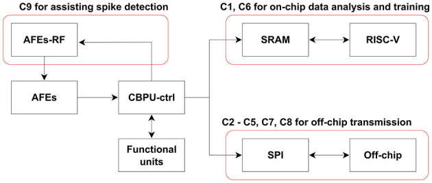
Figure 3.

Data flow and active blocks depicting various commands. In addition to the labeled block in the diagram, each command involves the Central Bio-Signal Processing Unit control logic and corresponding functional units. For commands C1 and C6, the process comprises a recording phase followed by an analysis/training phase. During the recording phase, the RISC-V remains in sleep mode to conserve power.
