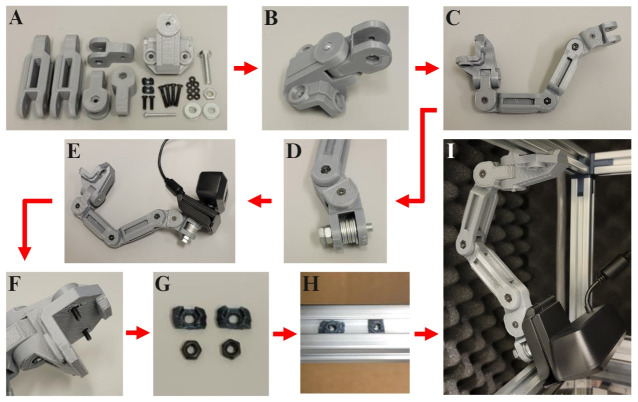
Figure 2. Instructions for assembling the camera mount.
A) Gather the 3D-printed camera mount pieces, M3 10 mm machine screws (2×), M3 20 mm machine screws (4×), M3 30 mm machine screw (1×), M3 nuts (7×), ¼ in. diameter 20 threads/inch 1 in. long bolt (1×) with corresponding nut (1×) and washers (8×), and camera (1×). B) Connect the T-Slot mounting piece to the first segment of the articulating arm with the M3 30 mm screw and nut. C) Connect the remaining articulating arm pieces with the M3 20 mm screws and nuts. D) Thread the 1 in. bolt through the last articulating arm segment with a nut at the bolt’s base and eight washers filling the gap. E) Screw in the camera’s base to the threaded end of the exposed 1 in. bolt. F) Place two of the M3 10 mm screws through the holes of the plastic T-Slot rail mounting piece. G) Fit an M3 nut into each of the two small T-Slot rail adapter pieces. H) Slide the assembled T-Slot rail adapter pieces into the groves of the T-Slot rail (left) and rotate them 90° to lock them into place (right). I) Align the M3 10 mm screws within the T-Slot rail mounting piece with the T-Slot rail adapter pieces and screw them in, mounting the camera arm to the rail.

