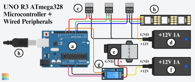
Figure 4. Wiring diagram between the microcontroller and peripherals.
a) ATmega382 UNO R3 microcontroller. b) 12V 4-pin RGB LED strip with four contact pads labeled from top to bottom: +12V power (+), red LEDs (R), green LEDs (G), and blue LEDs (B). c) TIP120 transistors with three pins labeled from left to right: base (B), collector (C), and emitter (E). d) 12V 1A DC power supply for the RGB LED strip with two wires labeled from top to bottom as ground (GND) and positive (+12V). e) Pneumatic solenoid with two wires labeled from left to right as ground (GND) and positive (+). f) 12V 1A DC power supply for the pneumatic solenoid with two wires labeled from top to bottom as ground (GND) and positive (+12V). g) 5V activation relay module with three pins labeled on the left-hand side of the device from top to bottom as signal (S), ground (G), and Vcc (V); three screw terminals labeled on the right-hand side of the device from top to bottom as normally closed (NC), common (COM), and normally open (NO). h) USB type-B cable for supplying power to the microcontroller alongside data communication with the computer.

