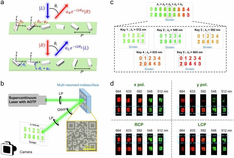
Fig. 5. Vectorial holographic imaging with multi-resonant metasurfaces.
a Two sets of PB phase gradient metasurfaces with opposing orientation angle increments. This design is intended to deflect both LCP and RCP images at the same angle, enabling controllable amplitude and phase distributions. The goal is to create a vectorial holographic image. b Schematic illustration of the optical setup used to experimentally characterize the holographic imaging of multi-resonant metasurfaces. The inset shows an optical microscope image of the fabricated sample. The images displayed on the screen schematically illustrate the expected results when the metasurface is illuminated by a 512 nm laser and characterized under circular polarization states. The gray dashed region indicates the designed observation position for information decryption. LP linear polarizer, QWP quarter-wave plate, AOFT acousto-optic tunable filter. c Schematic for the comprehensive vectorial holographic imaging at five peak wavelengths. All images spatially overlap when illuminated with five laser wavelengths simultaneously (top panel). When images are captured at the same spatial position (highlighted by the gray dashed rectangles in the bottom panel), distinct images emerge upon switching the laser wavelength. In each image, the numbers in the first row correspond to circular polarizations, while those in the second row correspond to linear polarizations. As an example, only the images in the first row, representing LCP states, are clearly observed in the bottom panel. d Experimental results of the vectorial holographic imaging at the designed observation angle. The bottom regions of each image correspond to the linear polarization channel, while the top regions are designated for circular polarization states. The dashed rectangles highlight the locations where the target numbers are expected to appear when all conditions (incident wavelength, polarization states, and observation angle) are met. More results can be found in Supplementary Fig. 18.

