
Figure 2.
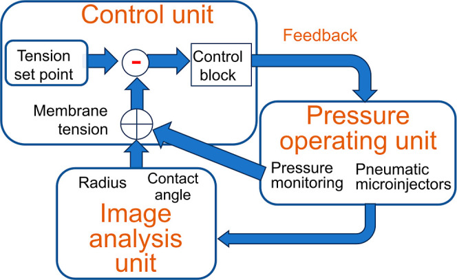
General schematic of the membrane tension-clamp system established on the CBB system. Here, each bubble system is depicted, which is integrated to manage bilayer tension in the CBB. The bubble system comprises three subsystems: the pressure-operating unit (for pressure measurement and application), the image analysis unit, and the control unit. To clamp membrane tension, real-time tension evaluation is essential. Image-processing techniques are used to deduce bubble geometry (radius of bubbles and contact angle between bubbles). The bubble geometry data and pressure values are combined to assess leaflet and bilayer tension. In the control unit, deviations of measured values from a set point value are processed through the control block, involving the proportional-integral-derivative (PID) controller, yielding feedback signals. The feedback signals are sent to the bubble pressure controller (a pneumatic microinjector), finely tuning the bubble pressure via a stepping motor.