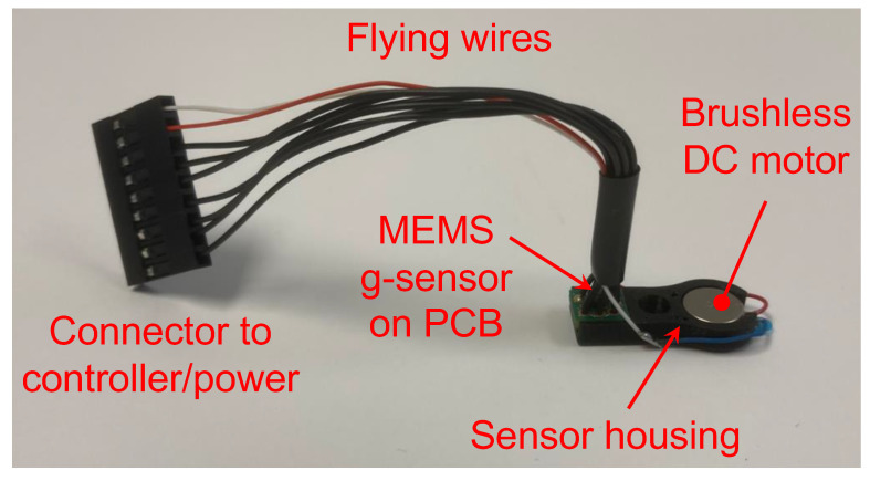
Figure 2.
The sensor assembly built to measure the flex constants comprised a brushless DC motor, a MEMS-based accelerometer (aka g-sensor), a sensor housing, a set of flying wires, and a connector to a controller and a power source. The motor and the accelerometer were seated snugly in the housing. Through a central hole of the housing, the angular stiffness sensor set was press-fit onto the locator abutment. The motor generated a known eccentric force, gently wiggling the locator abutment. The accelerometer measured the acceleration of the locator abutment. The measured acceleration was forwarded to the controller for post-processing to extract angular stiffness.

