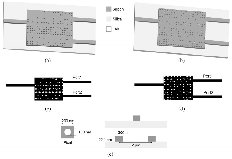
Figure 2.
Structures of the passive phase shifters. (a) 3−D structural schematic of the TE mode device. (b) Top view of the TE mode device. (c) 3−D l structural schematic of the TM mode device. (d) Top view of the TM mode device. (e) Top view of a pixel and side view of the input and output waveguides.

