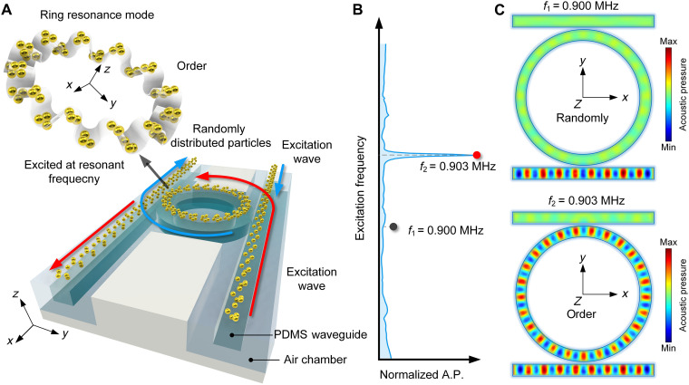
Fig. 1. Acoustofluidic tweezers via ring resonance.
(A) Schematic diagram shows the positioning on both sides of the PDMS waveguide, inducing clockwise (CW) and counterclockwise (CCW) resonances in the RR due to the red and blue input signals, respectively. The particles, which are initially randomly distributed throughout the channel, will be transformed to an ordered state by ring resonance mode in the RR, enabling particle patterning. (B) Nonresonant and resonant frequencies of the RR are marked at f1 = 0.9 MHz and f2 = 0.903 MHz, respectively. (C) Acoustic field distribution at 0.9 MHz (nonresonant mode) and 0.903 MHz (resonant mode). A.P., acoustic pressure.

