. 2024 Nov 7;24(24):5360–5373. doi: 10.1039/d4lc00659c

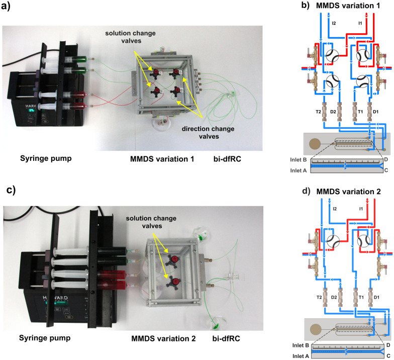
Fig. 2. MMDS variations for the delivery of treatments following solution and/or directional change into the bi-dfRC microchannel. Low-Pressure Unions are labelled T1–T2 and D1–D2. (a) Syringe pump and MMDS variation 1 for delivery of test solutions into the bi-dfRC microchannels, harboring solution and directional change manual switching valves set to deliver full treatment (green) at the shoot site (differentiation zone). (b) Schematic diagram depicting the MMDS1 tubing array and the flow path for the application of a full treatment one (blue) through inlets A & B of the bi-dfRC at the shoot site. (c) Syringe pump and MMDS variation 2 for delivery of test solutions into the bi-dfRC microchannels, equipped with a single pair of solution change manual switching valves set to deliver full treatment (green) at the shoot site. (d) Schematic diagram depicting the MMDS2 tubing array and the flow path for the application of a full treatment one (blue) through inlets A & B of the bi-dfRC at the shoot site.

Fig. 2