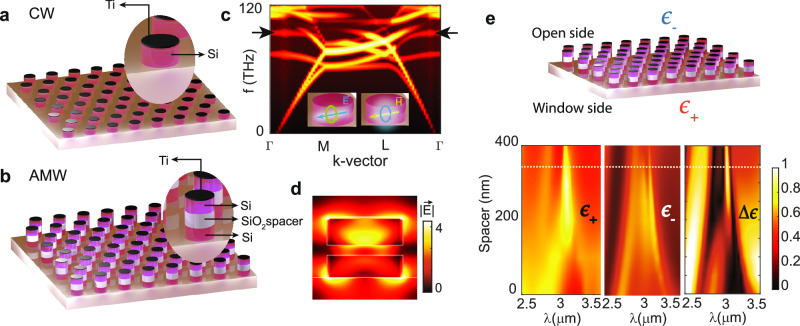
Fig. 2. Design for the control window (CW) and the asymmetric meta-window (AMW).
Schematic of (a) CW and (b) AMW with insets showing the individual resonator structure. c Calculated TM band structure of a hexagonal array of cylindrical silicon resonators with a period of 2 μm, height of 600 nm, and radius of 700 nm, showing a QBIC mode as a flat band (marked with black arrows) near the Γ point. The insets describe the magnetic and electric dipolar modes excited in each resonator that interfere to create the QBIC mode. d The calculated cross-sectional electric field profile at the resonance (λ = 3.06 μm) of the AMW resonators with a spacer thickness of 350 nm (weak coupling), showing very different field strengths in the two resonators. e Normal direction emissivity (ϵ) from the AMW toward the window side (higher emissivity, ϵ+), open side (lower emissivity, ϵ−) and Δϵ as a function of spacer thickness. The horizontal white line marks the spacer thickness (350 nm) considered in (d).

