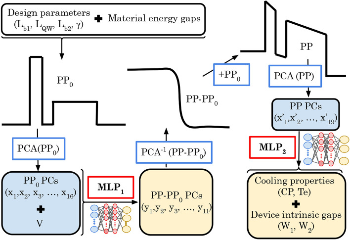
Fig. 2.
Machine learning procedure. From the combination of the design parameters ( ) and the material energy gaps, the first solution of the potential profile (
 ) is constructed, and its features are reduced by applying the principal component analysis (PCA(PP0)) to obtain the
  principal components (
 ). The
 combined with the V are the inputs of the first multi-layer perceptron (MLP1), which gives the difference between potential profile (PP) and
  (PP-PP0)
  as the output. The PP of the device is obtained by applying the inverse principal component analysis (PCA) (
 (PP-PP0) and adding the PP0. The inputs of the second multi-layer perceptron (MLP2) are the PP
  obtained from the application of PCA(PP) to the PP. Finally, the MLP2 provides, as output the information about the cooling properties (CP,
  ) and the device activation energies (
 ,
,  ).
).

