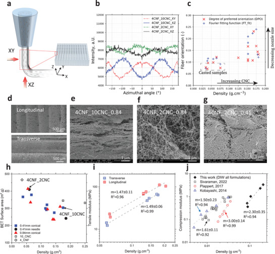
Figure 2.

Alignment of the structure of cellulose aerogel during the printing. a) Schematic representation of the printed filament directions the potential alignment of the cellulose nanofibers. b) Radial integration of SAXS profiles for two different CNC concentrations (in the range of 0.3 < q < 1 nm‐1), with X (dashed lines) and Y (solid lines) filament showing a phase difference of 90°. c) Fiber orientation using DPO and FT_fit for DIW‐aerogels as a function of density. d) The printing filament directions. Microstructure of the printed objects with e) ink 4CNF_10CNC and nozzle size 0.84 mm, f) ink 4CNF_2CNC and nozzle size 0.84 mm, g) ink 4CNF_2CNC and nozzle size 0.41 mm. h) Specific surface area for different CNF‐CNC aerogels using different nozzle types. Open symbols are CNF‐ and CNC‐only samples. i) Tensile modulus of the objects tested from transverse or longitudinal directions. j) Compression modulus as a function of density for the DIW printed aerogels and a comparison with reported mold‐casted cellulose aerogels.[ 19 , 21 , 22 ]
