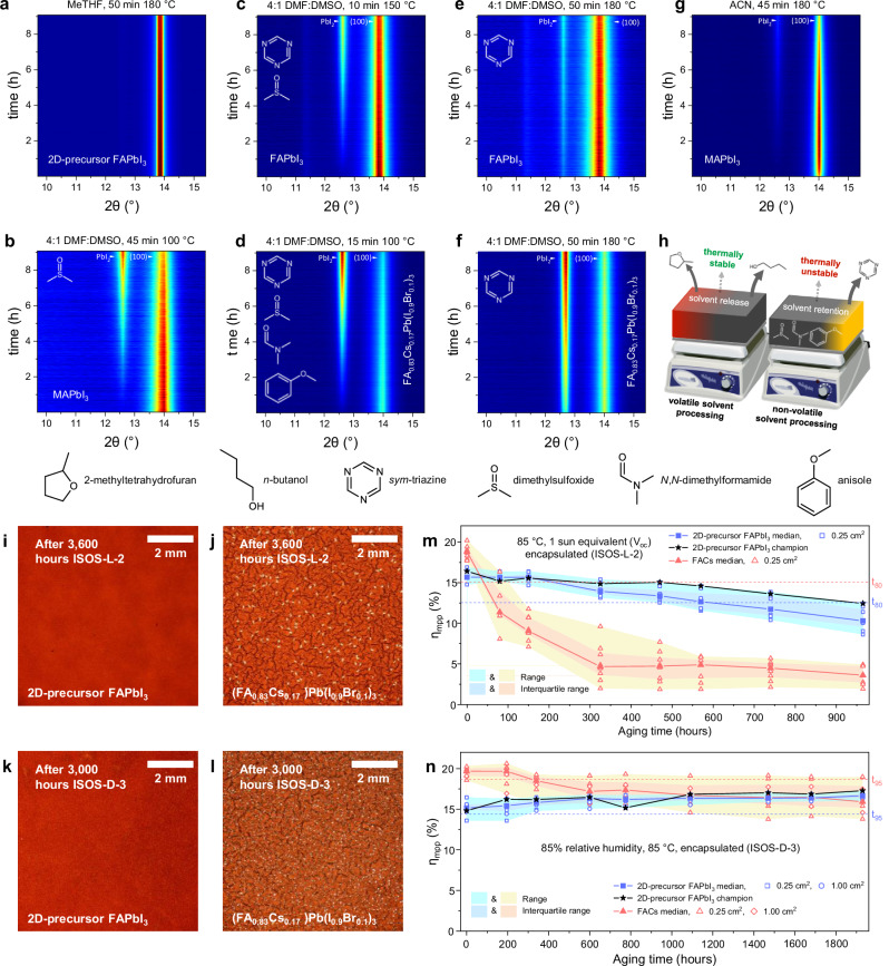
Fig. 5. Enhanced perovskite stability.
a–g Contour maps depicting in-situ x-ray diffraction (XRD) analysis of perovskite materials thermally degrading whilst held at 130 °C for 9 hours. Labels indicate perovskite composition and fabrication conditions (solvent, thermal curing). Full processing conditions described in Supplementary Note 6. Molecular structures shown correspond to the volatile species detected during thermal desorption-gas chromatography-mass spectrometry (TD-GCMS) analysis of each perovskite. h Schematic highlighting advantages to perovskite material properties of solution processing via MeTHF solvent system. Visible light microscopy images of encapsulated state-of-the-art perovskite thin films after aging for 3600 hours under 85 °C, 1-sun equivalent illumination (ISOS-L-2, i-j) and 3000 hours under 85 °C, 85 % relative humidity (ISOS-D-3, k, l) conditions. Evolution under ISOS-L-2 (m) and ISOS-D-3 (n) stressing of maximum power tracked efficiency (ηmpp) measured periodically on p-i-n PSCs employing 2D precursor phase-engineered FAPbI3 (7 cells and 8 cells, respectively) and FA0.83Cs0.17Pb(I0.9Br0.1)3 (8 cells, under each condition, “FACs”) as the photoactive layer. Cells undergoing ISOS-L-2 are encapsulated with a 250 nm layer of MoO3 followed by an on-cell epoxy resin and cover slip. Cells undergoing ISOS-D-3 are encapsulated in glass-glass laminates employing an industry standard butyl-rubber edge sealant (described in Supplementary Note 10). Dashed lines show the median t80 ηmpp values for each dataset. The median, range and interquartile range of each dataset are shown, as well as each data point within them.

