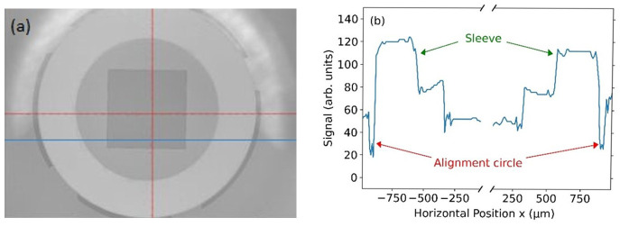
Figure 5.
( a) Microscope image of the sleeve attached to the silicon substrate. On the substrate alignment circles have been fabricated at the positions corresponding to the outer diameter of the sleeve. The red cross just marks the center of the camera image. ( b) Intensity image values in arbitrary units along the blue line in ( a). The alignment circles with a nominal width of 50 µm can be seen at the left- and right-hand side of the plot. The measured width of both alignment circles differs by less than 15 µm, which denotes the alignment accuracy of the sleeve and thus of the fiber-chip coupling. The measured width of both alignment circles is used to extract a standard uncertainty of 9 µm, see main text.

