Abstract
For sodium-ion batteries, solving the issue of short cycle life is key to their large-scale adoption in the industry, and the electrolyte plays an important role on this. Herein, this work aims to design a practical sodium ion battery electrolyte with industrial application value and introduces anhydride compounds as additives for the first time. Meanwhile, by adjusting the solvent composition and using a combination of ether and ester solvents, the optimal electrolyte formulation of 1 M NaPF6 (sodium hexafluorophosphate) + DME (glycol dimethyl ether)/VC (vinylidene carbonate) (1 : 1, v/v) + 2 wt% GA (glutaric anhydride) is designed. Na+-VC, which has the highest occupied molecular orbital in this electrolyte, is preferentially oxidized to form a cathode electrolyte interface on the cathode. And synchronously, Na+-GA with the lowest unoccupied molecular orbital is preferentially reduced to form a surface electrolyte interface on the anode. This electrolyte can achieve simultaneous film formation on both sides of the electrode, thus greatly increasing the cycle life of the sodium-ion battery. For example, the Na‖NVP (sodium vanadium phosphate) battery still maintains a specific capacity of 91.16 mA h g−1 with a capacity retention rate of 85.06% after 2500 cycles. And the NVP‖HC (hard carbon) full battery also maintains a capacity retention rate of 66.50% after 800 cycles. This work will provide important ideas and strong evidence for the industrial application of sodium ion battery electrolytes with long cycle life.
For sodium-ion batteries, solving the issue of short cycle life is key to their large-scale adoption in the industry, and the electrolyte plays an important role on this.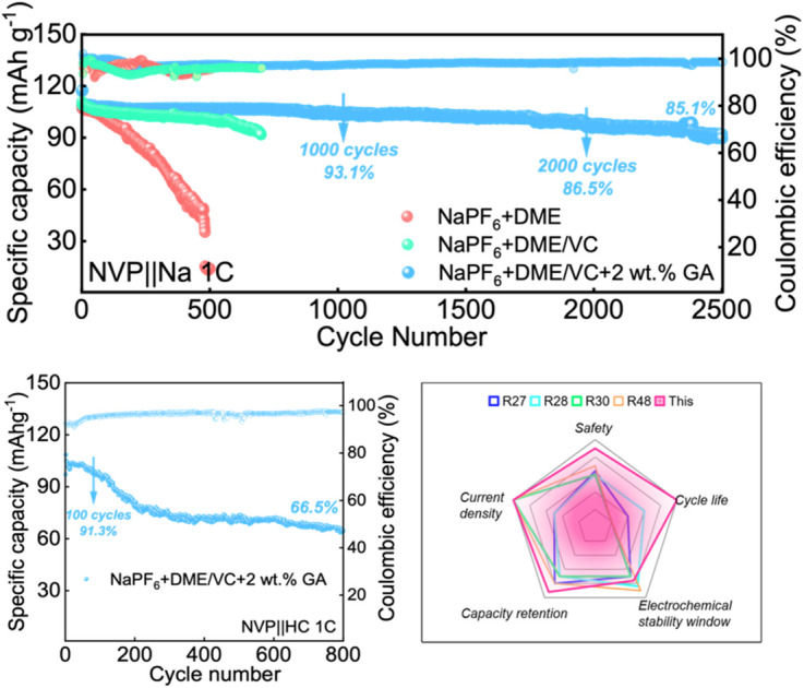
Introduction
Compared with lithium-ion batteries (LIBs), sodium-ion batteries (SIBs) offer advantages of low cost and a wide range of material sources and are expected to become an alternative for energy storage and power (low-speed) systems in the future.1–5 As is well known, the crustal abundance of sodium is about 2.36%, which is much higher than that of lithium (0.002%). Meanwhile, the price of sodium compounds is stable and low, far lower than the price of battery-grade lithium carbonate. Additionally, the electrochemical performance of SIBs is relatively stable and safer.6–9
As an important part of SIBs, the function of electrolyte is to transfer charge between the cathodes and anodes, which is crucial to the specific capacity, operating temperature range, cycle efficiency, safety performance, production cost of the battery, etc.10–12 Generally, the electrolyte of SIBs is mainly composed of conductive sodium salts, organic solvents, and functional additives. The commonly used sodium salts are sodium hexafluorophosphate (NaPF6), sodium perchlorate (NaClO4), sodium hexafluoroarsenate (NaAsF6), sodium tetrafluoroborate (NaBF4), sodium difluoroxalate borate (NaBOB), etc. and the organic solvents are generally alkyl carbonate compounds.13,14 The electrochemical performance and safety of SIBs are simultaneously affected by the electrolyte, which not only determines the electrochemical window and energy density of the battery, but also controls the properties of the electrode/electrolyte interface.15,16 The complex electrochemical side reactions of electrolyte and the formation of metallic sodium dendrites limit the development of SIBs to some extent.
Currently, the research on electrolyte in SIBs mainly focuses on new electrolyte salts, solvent modification and mixing, new additives, etc. A series of new sodium salts, such as sodium difluoroacetate sulfonimide (NaFSI), sodium trifluoromethyl sulfonimide (NaTFSI), sodium difluoroacetate borate (NaODFB), etc. have been proven to be potential alternatives.17–19 Compared with traditional carbonate solvents, ethers serve as alternatives in the electrolyte of SIBs.20 In addition, nitriles, fluorinated solvents, carboxylate solvents, ionic liquids can also serve as candidate solvents. Especially, owing to their excellent film forming properties, high and low temperature stability, fast charging capabilities, new additives have become the focus of researchers in recent years.21,22 In SIBs, the film-forming component NaF is relatively easy to dissolve during the reaction process, making the electrode interface unstable.23 In general, the unstable electrolyte interface is rapidly consumed in the long-term cycle process, correspondingly leading to the gradual decomposition of the electrolyte and severe side reactions between the electrolyte and the electrode. These factors will further lead to irreversible capacity attenuation, and therefore it is very valuable to construct a stable electrode interface in SIBs.24,25
Among the new additives, anhydride molecules can generally be regarded as oxides formed by the dehydration of acid and they have excellent film forming properties on the electrode surface.26 Fan et al. used succinic anhydride as a strengthening film additive for vinyl fluorocarbonate to improve the cycle life of the battery, with a capacity retention rate of 87.2% after 400 cycles at a current density of 1C.27 Xie et al. found that lithium dendrites are generated uncontrollably during the battery cycle, and the addition of succinic anhydride can improve the energy barrier of Li+ deposition and inhibit the formation of lithium dendrites.28 According to the study by Dai et al. the additive diethylene glycol anhydride could form a strong electrode interface at both the cathode and anode, protecting the structure of the material and extending the life of the battery.29
However, the application of anhydride additives in SIBs has not been reported, and the easy-oxidation ability of ether-based electrolytes also needs to be regulated by co-solvents to harness their advantages while avoiding disadvantages.30 In this work, glutaric anhydride (GA) was selected as a special additive, and the solvent formulation was adjusted by mixing the ether solvent glycol dimethyl ether (DME) with the film effective ester solvent vinylidene carbonate (VC). Na+-VC, which has the highest occupied molecular orbital (HOMO) in this electrolyte, is preferentially oxidized to form a cathode electrolyte interface (CEI) on the cathode. And synchronously, Na+-GA with the lowest unoccupied molecular orbital (LUMO) is preferentially reduced to form a solid electrolyte interface (SEI) on the anode. Therefore, the optimal electrolyte formulation in this work is designed to form a uniform and dense special electrode interface to improve the cycle performance of SIBs.
Experimental section
Materials and chemicals
Battery-grade sodium hexafluorophosphate (NaPF6, purity ≥ 99.9%), glycol dimethyl ether (DME, purity ≥ 99.9%), vinylidene carbonate (VC, purity ≥ 99.9%) and glutaric anhydride (GA, purity ≥ 99.9%) were all purchased from Maclin Biochemical Technology Co., Ltd, China. Before using, all solvents were dehydrated using 4 Å molecular sieves (activated in a muffle furnace at 550 °C for 4 hours). The commercial sodium vanadium phosphate (NVP), polyvinylidene fluoride (PVDF), acetylene black and N-methyl-2-pyrrolidone (NMP) were all purchased from Taiyuan Lishiyuan Chemicals, China. Metal sodium, hard carbon (HC) and other electrode materials were provided by Sinopod Chemical Reagent Co., Ltd, China.
Electrolyte preparation and battery assembly
In our work, the electrolyte preparation and battery assembly were carried out in a glovebox (IGBS1200) filled with an argon atmosphere, maintaining water and oxygen contents below 0.01 ppm. With the goal of a simple and pure electrolyte design, the optimal electrolyte was prepared by dissolving NaPF6 (the only electrolyte salt) in a mixture of DME (the only solvent), VC (the cathode film forming additive) and GA (the anode film forming additive). The specific formulations are presented as follows: 1 M NaPF6 + DME (E0), 1 M NaPF6 + DME/VC (1 : 1, v/v) (E1), and 1 M NaPF6 + DME/VC (1 : 1, v/v) + 2 wt% GA (E2). When assembling SIBs, the commercial NVP, 4 wt% PVDF, and acetylene black were thoroughly mixed in a mass ratio of 8 : 1 : 1 and stirred in a solder paste mixer (SMT) for 20 minutes. The above as-formed slurry was coated on aluminum foil, and then dried in a vacuum oven at 120 °C for 12 hours. Sodium metal or hard carbon was applied as the anode and a glass fiber diaphragm (Whatman) with a thickness of 260 μm was applied the separator. The mass loadings of the electrodes were calculated to be between 2.50–3.00 mg cm−2. In this work, each battery was tested with the same amount of electrolyte (65 μL).
Battery testing and characterization
In the voltage range of 2–3.8 V, the as-assembled SIBs were activated first with a current density of 0.1C for three cycles, and then tested at 0.5C and 1C cycles respectively using a Neware (CT-4008T-5V12A-S1-F) battery tester. Cyclic scanning voltammetry (CV) and linear scanning voltammetry (LSV) were conducted using an electrochemical workstation (CH1660E) at a scanning speed of 0.1 mV s−1. High resolution transmission electron microscopy (HRTEM, FEI Tecnai G20) was used to characterize the surface morphology of the cathode and anode after cycling. Infrared spectroscopy (Nicolet Is 10) and Raman spectroscopy (United States-Thermo Fisher-Dxr 2xi) were applied to analyze the solvent composition of the electrolyte, and an X-ray photoelectron spectrometer (XPS, United States-Thermo Scientific-ESCALAB Xi+) was used to test the composition of the film formed on the cathode and anode after cycling.
Results and discussion
The design of electrolytes
In SIBs, the electrode/electrolyte interface phase is an important component of the reversible reaction that keeps the battery away from thermodynamic equilibrium, and the solid electrolyte film is one of the important components of the interface phase.31 However, the chemical composition and morphology of this interface phase are still controversial, and most researchers do not fully understand its composition, formation process and mechanism of action. Generally, a solid electrolyte film has a kind of double-layer structure with a thin inner layer and a slightly thick outside layer. In actual batteries, the solid electrolyte film cannot completely inhibit the further decomposition of the electrolyte, and the resulting irreversible capacity loss is a major problem affecting the battery cycle life.32
The design optimization and regulation of the electrode interface cannot achieved by a single species for the best result. The electrolyte sodium salts can achieve the preferential oxidation or reduction at the cathodes and anodes, facilitating the formation of a dense solid film.33,34 Electrolyte solvents usually need to have high a dielectric constant, low viscosity, good chemical stability, suitable melting boiling point, etc. The additives can also be coated on the electrode surface through a series of chemical reactions or electrochemical reactions to improve the high and low temperature performance of the battery.35
In this work, with the goal of a simple and pure electrolyte design, NaPF6 is adopted as the only electrolyte salt, DME as the only solvent, and VC as the cathode film forming additive and GA as the anode film forming additive. The specific formulations are presented as follows: 1 M NaPF6 + DME (E0), 1 M NaPF6 + DME/VC (1 : 1, v/v) (E1), and 1 M NaPF6 + DME/VC (1 : 1, v/v) + 2 wt% GA (E2).
The DFT calculations and solvation structures of electrolytes
In designing the electrolyte formulations, the solvents are initially selected based on the usage requirements by referring to characteristics of various solvents statistically compiled in previous literature. The rationality of the electrolyte formulation is verified through theoretical calculations of different molecules and ions, and DFT calculations are carried out by comparing the redox behavior of electrolyte components from the perspective of thermodynamics.36,37
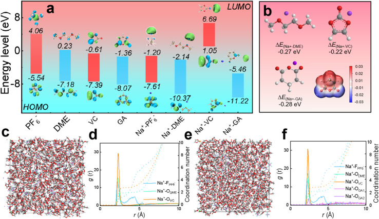
As displayed in Fig. 1a, the HOMO values of PF6−, DME, VC, GA, Na+-PF6−, Na+-DME, Na+-VC, and Na+-GA are −5.54, −7.18, −7.39, −8.07, −7.61, −10.37, 1.05 and −11.22 eV, respectively. The LUMO values are 4.06, 0.23, −0.61, −1.36, −1.20, −2.14, 6.69 and −5.46 eV, respectively. It is worth noting that the higher the HOMO value of the molecule, the more easily it is oxidized at the cathode, and the lower the LUMO value of the molecule, the more easily it is reduced at the anode.38,39 Therefore, in our electrolyte formulation, VC bound with sodium ions tends to be preferentially oxidized at the cathode to form CEI films from a thermodynamic perspective. Similarly, GA combined with sodium ions tends to be preferentially reduced to form a SEI film at the anode. The possibility of film formation by GA can be also evaluated from the adsorption energy of GA, as shown in Fig. 1b. The adsorption energy of GA (−0.28 eV) is lower than that of DME and VC, so GA tends to be preferentially adsorbed on the anode, and then decomposed to form the SEI film.40Fig. 1b also presents the molecular electrostatic potential (ESP) of the GA additive, revealing the solvation ability of GA. On one hand, the O atoms in GA molecules exhibit a negative charge density, making it easier for them to interact with Na+. On the other hand, the high electrostatic potential of O in GA confirms its weak solvation ability, and the solvent occupies the first solvent sheath, with GA appearing outside the first solvent sheath.41 In summary, GA hardly participates in solvation and retains its inherent chemical properties.
Fig. 1. DFT calculations of electrolytes. (a) The HOMO and LUMO values of PF−6, DME, VC, GA, Na+-PF6−, Na+-DME, Na+-VC and Na+-GA. (b) The adsorption energy of Na+ with DME, VC, and GA, and the molecular electrostatic potential (ESP) of the GA additive. (c–f) Molecular dynamics simulations: (c) snapshot and (d) radiation distribution function and coordination number of the electrolyte without the GA additive; (e) snapshot and (f) radiation distribution function and coordination number of the electrolyte with the GA additive.
According to the radial distribution function calculations, the peaks of DME solvent, VC and some NaPF6 salt in the electrolyte without the GA additive in Fig. 1c and d appear around 2.27 Å, verifying that these solvents and salt enter the first solvent shell, and some NaPF6 salt exhibits peaks around 4.21 Å, corresponding to the second solvent shell. From the coordination number, it can be calculated that the solvation unit of the electrolyte without the GA additive is Na+[DME]2.74[VC]1.79.42 In the electrolyte after adding GA as an additive, as shown in Fig. 1e and f, the peaks of the DME solvent, VC and some NaPF6 salt appear around 2.27 Å and the peak corresponding to a small amount of GA additive also appears, confirming that these salts, solvents and the additive enter the first solvent shell. Some NaPF6 salt peaks appear around 4.21 Å, indicating that they enter the second solvent shell and the solvation structure is Na+[DME]2.85[VC]1.95[GA]0.28 based on the coordination number. From the results of the radial distribution function, it can be concluded that the GA additive hardly participates in solvation coordination.
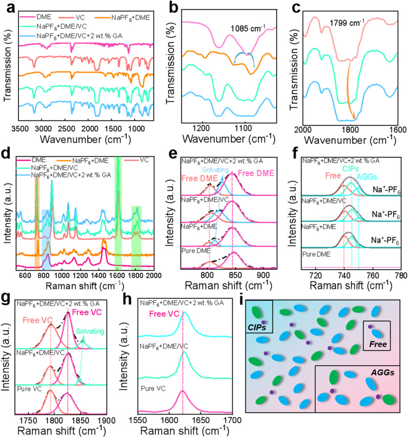
From the FTIR spectra, it can be observed that after adding NaPF6 to pure DME, the peak around 1085 cm−1 is split into two new peaks, as shown in Fig. 2a and b. The appearance of these new peaks indicates the influence of the coupling interaction between C–O–C and Na+ on the C–O–C tensile vibration in DME solvent molecules.43,44 This interaction allows DME to fully dissolve Na+ to prevent ion pairing, and this effect becomes more obvious after the addition of the co-solvent VC. Additionally, from the characteristic peaks of VC in Fig. 2c, the peak at 1799 cm−1 tends to slightly shift to a higher wave number after the addition of NaPF6 and DME, forming Na+-VC. It must be highlighted that these two changes are not particularly obvious after the addition of the GA additive. Each characteristic peak of Raman spectra also displays the obvious solvation phenomenon.45 In Fig. 2d showing the overall Raman spectra, the peak areas framed in orange, blue and green represent the characteristic peak areas of NaPF6, DME and VC, respectively. With the addition of NaPF6, the solvation peak of Na+-DME appears in the characteristic peak of DME as observed in Fig. 2e, and this solvation effect becomes more obvious with the addition of VC and GA. In Fig. 2f showing the NaPF6 Raman spectra, it can be found that the Raman peaks are composed of free anions, contact ion pairs (CIPs: PF6− coordinated with a single Na+), and aggregates (AGGs: PF6− coordinated with two or more Na+).46,47 As presented in Fig. 2g and h, upon adding the NaPF6 salt and GA additive, the C C peak of VC around 1625 cm−1 shifts. The solvation peak of Na+-VC appears to the right of the characteristic peak of C O around 1700–1850 cm−1. Fig. 2i shows the simulation of all the solvated structures in the electrolyte combined with calculations and tests.
Fig. 2. The solvation structures of electrolytes. The FTIR spectra of different electrolytes in the range of (a) 600–3500 cm−1, (b) 1025–1250 cm−1 and (c) 1600–2000 cm−1. Raman spectra of different electrolytes in the range of (d) 500–2000 cm−1, (e) 760–920 cm−1, (f) 710–780 cm−1, (g) 1720–1900 cm−1 and (h) 1550–1700 cm−1. (i) The simulation of all the solvated structures in the electrolyte combined with calculations and tests.
The electrochemical performance of electrolytes
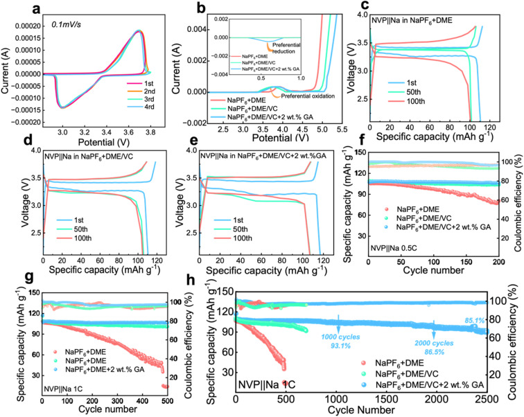
To investigate the electrochemical performance of the designed electrolytes, the voltammetry characteristics were first characterized. The CV test was carried out on a Na‖NVP battery with the electrolyte containing 2 wt% GA, and it can be seen from Fig. 3a that the battery maintains good cycle reversibility under this electrolyte. From the LSV results in Fig. 3b, the electrochemical window of the electrolyte is obviously broadened after the introduction of VC, verifying that the addition of ester solvent VC can effectively inhibit the oxidative decomposition of the ether solvent DME. Meanwhile with the addition of VC, the oxidation peak originally located at 3.8 V shifts significantly to around 3.3 V, fully confirming that the addition of VC can achieve preferential oxidation. Additionally in the inset of Fig. 3b, a reverse peak appears at about 0.6 V after the introduction of the GA additive, proving the preferential reduction of GA. The preferential reduction of GA inhibits the reduction of the electrolyte itself. These two phenomena further verify the results obtained from the calculations that VC is preferentially oxidized to form a CEI film at the cathode and GA is preferentially reduced to form a SEI at the anode.
Fig. 3. The electrochemical performance of electrolytes. (a) The 1st–4th CV curves of the Na‖NVP battery in the electrolyte containing 2 wt% GA additive. (b) The LSV curves of the Na‖NVP battery in the three electrolytes. (c–e) The corresponding galvanostatic charge/discharge curves of the three Na‖NVP batteries at different cycles. The cycle performance of Na‖NVP batteries in different electrolytes (f) for 200 cycles at 0.5C and (g) for 500 cycles at 1C and (h) for 2500 cycles at 1C.
From the charge and discharge curves in Fig. 3c and e, it can be observed that the initial capacities of the batteries assembled with the three electrolytes are not much different. After 100 cycles, the capacity of the battery with 2 wt% GA electrolyte at 1C current density is higher than that of the batteries assembled with the other two electrolytes. The initial coulombic efficiencies of these three batteries are 98.04%, 93.54%, 99.89% for E0, E1 and E2 electrolytes, respectively. The cycle performance of Na‖NVP batteries composed of different electrolytes is also investigated. Firstly, the Na‖NVP batteries were activated for three cycles at a current density of 0.1C and then 200 cycles were performed at a current density of 0.5C; as shown in Fig. 3f the specific capacity of the battery with the NaPF6 + DME electrolyte after 200 cycles is 89.76 mA h g−1 with a capacity retention rate of 83.9%, exhibiting obvious attenuation. The capacity of the battery in NaPF6 + DME/VC electrolyte exhibited attenuation, with a specific capacity of 103.77 mA h g−1 after 200 cycles, and a capacity retention rate of 95.1%. The battery with NaPF6 + DME/VC/GA electrolyte retained a specific capacity of 106.34 mA h g−1 and a capacity retention rate of 99.2% after 200 cycles at 0.5C. Secondly, after activating the batteries in the three electrolytes three times at 0.1C, the cycle test was carried out at 1C; as displayed in Fig. 3g, the NaPF6 + DME battery had a specific capacity of only 14.7 mA h g−1 after 500 cycles. After adding the co-solvent VC, the NaPF6 + DME/VC battery achieves a specific capacity of 100.95 mA h g−1 after 500 cycles with the capacity retention rate of 91.6%. After adding 2 wt% GA as an additive, the NaPF6 + DME/VC/GA battery maintains a specific capacity of 106.65 mA h g−1 and a capacity retention rate of 99.5% after 500 cycles. What is particularly impressive is that, after 2500 cycles, as shown in Fig. 3h, the NaPF6 + DME/VC/GA battery still has a specific capacity of 91.16 mA h g−1 and a capacity retention rate of 85.1%. These electrochemical properties can convincingly verify the long-term cycle stability of the NaPF6 + DME/VC/GA electrolyte.
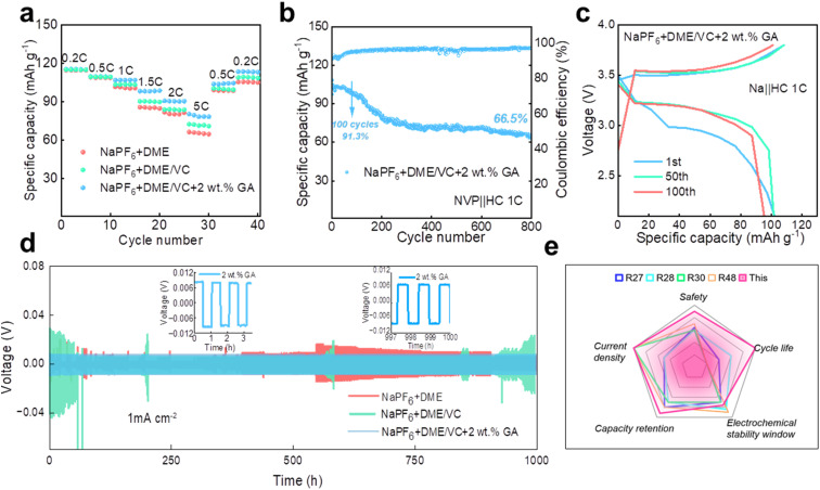
The rate performance of the Na‖NVP batteries in the three electrolytes is compared at the current densities of 0.2C, 0.5C, 1C, 1.5C, 2C and 5C, respectively. As shown in Fig. 4a, the rate performance of the electrolyte with 2 wt% GA additive is better than that of the other two electrolytes. To verify whether the electrolyte designed in our work is suitable for full batteries, sodium-ion full batteries based on hard carbon (HC) were assembled. It is worth noting that the N/P ratio for the sodium-ion full batteries is 1.03 : 1 in this work. Fig. 4b and c display the cycle performance and corresponding galvanostatic charge/discharge curves of the NVP‖HC battery in the electrolyte containing 2 wt% GA additive at 1C. Surprisingly, the full battery still demonstrates excellent battery performance, with an initial discharge capacity up to 104.8 mA h g−1. The initial coulombic efficiency of the full battery is 91.7%, and the subsequent coulombic efficiencies are all greater than 90%. Especially, the specific capacity of the NVP‖HC battery remains at 95.7 mA h g−1 after 100 cycles, demonstrating an outstanding capacity retention of 91.3%, and retaining over 66.5% after 800 cycles. To prove the long-term cycle feasibility of these three electrolytes, Na‖Na symmetrical batteries were assembled to evaluate the long-term stability at a current density of 1.0 mA cm−2. As exhibited in Fig. 4d, the electroplating voltages of the two electrolytes, NaPF6 + DME and NaPF6 + DME/VC, exhibit large fluctuations due to the formation of sodium dendrites, revealing that these two electrolytes are not suitable for long-term cycling. By contrast, the electroplating voltage of NaPF6 + DME/VC + 2 wt% GA remains consistently stable, confirming excellent long-term stability. Additionally, Fig. 4e compares the properties of the electrolyte designed by us with those reported in the literature. It can be observed that the as-designed electrolyte displays excellent performance in terms of cycle life, capacity retention, current density, safety, etc., satisfying the needs for practical applications.
Fig. 4. The electrochemical performance of electrolytes. (a) The rate performance of three Na‖NVP batteries. (b) The cycle performance and (c) corresponding galvanostatic charge/discharge curves of the NVP‖HC battery in the electrolyte containing 2 wt% GA additive at 1C. (d) Voltage-time profiles of the three Na‖Na symmetric cells at a current density of 1.0 mA cm−2. (e) Comparison of the properties of the electrolyte designed by us with those reported in the literature.48.
The mechanism analysis of electrolytes
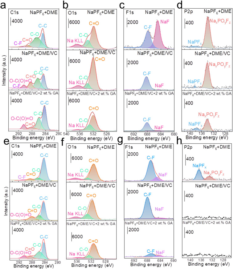
To investigate the influence of each electrolyte on the electrode interface, XPS tests were carried out on the active material composition of the cathode and anode after cycling in full batteries. In Fig. 5a, the C 1s spectra of NaPF6 + DME electrolyte present some peaks corresponding to decomposition products from the PVDF binder and acetylene black, located at 291.2 eV (–CF2–), 287.6 eV (C O), 286.0 eV (C–O), and 284.8 eV (C–C and C–H). The F 1s spectrum shows a peak at 687.4 eV (C–F) and the O 1s spectrum shows peaks at 531.5 eV (C O) and 533.8 eV (C–O). Obviously, the C 1s spectra of both NaPF6 + DME/VC and NaPF6 + DME/VC + 2 wt% GA electrolytes exhibit a new peak at 290.4 eV. This peak can be attributed to the functional effect of the two additives, VC and GA, that is, the open ring products of VC and GA (O–C(O) O), and the peak strength is slightly increased after adding GA.49 Meanwhile, the peak of C O indicates that the decomposition of DME is obviously inhibited with the addition of GA.50 In the O 1s spectra shown in Fig. 5b, it can be seen that the O content increases after adding VC, which is due to the film formation from the VC open ring on the cathode surface. However, the O content decreases after the addition of GA because the addition of GA can, on the one hand, inhibit the decomposition of DME, and on the other hand control the decomposition of VC, preventing the formation of an excessively thick electrode interface. As shown in Fig. 5c, the F 1s spectra reveal that the content of NaF decreases after the addition of VC and GA, indicating that the addition of these two substances inhibits the decomposition of PVDF, and the strength of C–F derived from the by-product decomposition is also significantly weakened. It can also be verified from the P 2p spectra in Fig. 5d that the P–O–F signal from by-products decreases after adding VC and GA.51 As can be seen from the film composition on HC anodes, a new O–C(O) O peak appears in the C 1s spectra similar to the spectra of the NVP cathodes. As shown in Fig. 5e, the appearance of this peak in the electrolyte results from the decomposition of VC and GA additives into films.52 In Fig. 5f, the O content increases in the O1s spectra, which is because the two additives, VC and GA, act together to form a film on the surface of the anode. In Fig. 5g, the F1s spectra show that the electrolyte containing 2 wt% GA effectively inhibits the decomposition of PVDF (C–F). And in Fig. 5h, the P 2p spectra prove that the addition of VC and GA significantly reduces the side reactions and decomposition of NaPF6.
Fig. 5. The composition characterization of CEI/SEI. XPS spectra of (a) C 1s, (b) O 1s, (c) F 1s, and (d) P 2p of NVP cathodes in three different electrolytes. XPS spectra of (e) C 1s, (f) O 1s, (g) F 1s, and (h) P 2p of HC anodes in three different electrolytes.
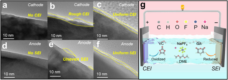
The electrode interface cycled in the three electrolytes can be observed using HRTEM images. Fig. 6a and d show that the NaPF6+DME electrolyte basically does not form a film on the cathode and anode, while Fig. 6b and e show that the NaPF6+DME/VC electrolyte forms a relatively rough film on the cathode and uneven film on the anode. In stark contrast to this, the NaPF6 + DME/VC + 2 wt% GA electrolyte forms relatively uniform and compact films in both the cathode and anode, as shown in Fig. 6c and f, again confirming the bipolar film formation of this electrolyte and its potential for long-term cycle stability.53 As illustrated in Fig. 6g, the CEI film is formed by preferential oxidation of VC on the cathode, and synchronously on the anode, GA is preferentially reduced to form the SEI film, confirming the potential for ultra-long-term cycle stability in SIBs.
Fig. 6. The mechanism analysis of electrolytes. HRTEM images of NVP in (a) 1 M NaPF6 + DME, (b) 1 M NaPF6 + DME/VC and (c) 1 M NaPF6 + DME/VC + 2 wt% GA electrolytes. HRTEM images of HC in (d) 1 M NaPF6 + DME, (e) 1 M NaPF6 + DME/VC and (f) 1 M NaPF6 + DME/VC + 2 wt% GA electrolytes. (g) The illustration of film formation on the cathode and anode in 1 M NaPF6 + DME/VC + 2 wt% GA electrolyte.
Conclusions
In this work, an anhydride additive is proposed for film formation in the SIB electrolyte, which can broaden the voltage window of ether solvent and facilitate film formation on the cathode as a co-solvent. That is, after adding VC as a co-solvent and 2 wt% GA as an additive to the basic electrolyte NaPF6 + DME, not only the voltage window is improved, but also the film formation on both electrodes is achieved, which correspondingly displays good cycle stability for SIBs. This outstanding performance can be mainly attributed to the fact that under the action of VC and GA, the electrolyte synchronously forms dense and uniform CEI and SEI films on the cathode and anode, respectively, thereby largely reducing the side reactions on both electrodes, thus achieving long-term stable operation of the battery.
Data availability
Essential data are fully provided in the main text.
Author contributions
Qin Zhou and Cong Xia: methodology, data curation, writing – original draft; Zhifan Kuang and Mengran Guo: formal analysis, investigation, software; Hao Zhang and Haojie Wan: validation, visualization; Jianwen Liu: conceptualization, funding acquisition; Lin Li: methodology, project administration; Shiquan Wang: software, supervision, writing-review and editing.
Conflicts of interest
There are no conflicts to declare.
Acknowledgments
This work was financially supported by the National Natural Science Foundation of China (No. 21978073), Hubei Key Research and Development Projects of China (No. 2023BAB148), the Open and Innovative Fund of the Hubei Three Gorges Laboratory (No. SK240004), the Wuhan metropolitan area collaborative innovation technology project (No. 2024070904020440) and the Joint Fund of Bijie City and Guizhou University of Engineering Science (BiKeLianhe[2023]12th). Technical support from Wuhan Jadechem Chemicals Co., Ltd, is also gratefully acknowledged. High-performance computing resources were also partially made available by Beijing PARATERA Technology Co., LTD.
References
- Rudola A. Sayers R. Wright C. J. Barker J. Nat. Energy. 2023;8:215–218. [Google Scholar]
- Yang Z. He J. Lai W. H. Peng J. Liu X. H. He X. X. Guo X. F. Li L. Qiao Y. Ma J. M. Wu M. H. Chou S. L. Angew. Chem. 2021;133:27292–27300. [Google Scholar]
- Qin Y. Choi S. G. Mason L. Liu J. Li Z. J. Gao T. Chem. Sci. 2024;15:9224–9239. doi: 10.1039/d4sc02266a. [DOI] [PMC free article] [PubMed] [Google Scholar]
- Wu C. Yang Y. R. Zhang Y. H. Xu H. He X. X. Chem. Sci. 2024;15:6244–6268. doi: 10.1039/d4sc00734d. [DOI] [PMC free article] [PubMed] [Google Scholar]
- Hirsh H. S. Li Y. X. Tan D. H. S. Zhang M. H. Zhao E. Y. Meng Y. S. Adv. Energy Mater. 2020;10:2001274. [Google Scholar]
- Liu T. F. Zhang Y. P. Jiang Z. G. Zeng X. Q. Ji J. P. Li Z. H. Gao X. H. Sun M. H. Lin Z. Ling M. Zheng J. C. Liang C. D. Energy Environ. Sci. 2019;12:1512–1533. [Google Scholar]
- Hu Y. S. Li Y. ACS Energy Lett. 2021;6:4115–4117. [Google Scholar]
- Singh A. N. Islam M. Meena A. Faizan M. Han D. Bathula C. Hajibabaei A. Anand R. Nam K. W. Adv. Funct. Mater. 2023;33:2304617. [Google Scholar]
- Vaalma C. Buchholz D. Weil M. Passerini S. Nat. Rev. Mater. 2018;3:18013. [Google Scholar]
- Qin Y. Choi S. G. Mason L. Liu J. Li Z. J. Gao T. Chem. Sci. 2024;15:9224–9239. doi: 10.1039/d4sc02266a. [DOI] [PMC free article] [PubMed] [Google Scholar]
- Ma M. Y. Chen B. B. Pan H. L. Chem. Sci. 2023;14:5983–5991. doi: 10.1039/d3sc01453c. [DOI] [PMC free article] [PubMed] [Google Scholar]
- Bolloju S. Vangapally N. Elias Y. Luski S. Wu N. L. Aurbach D. Prog. Inorg. Chem. 2024;147:101349. [Google Scholar]
- Liu J. W. He S. C. Liu S. Q. Wang S. Q. Zhang J. J. J. Mater. Chem. A. 2022;10:22929–22954. [Google Scholar]
- Tian Z. N. Zou Y. G. Liu G. Wang Y. Z. Yin J. Ming J. Alshareef H. N. Adv. Sci. 2022;9:2201207. doi: 10.1002/advs.202201207. [DOI] [PMC free article] [PubMed] [Google Scholar]
- Chen X. X. Yan S. S. Tan T. H. Zhou P. Hou J. X. Feng X. N. Dong H. Wang P. C. Wang D. Wang B. G. Ouyang M. G. Liu K. Energy Storage Mater. 2022;45:182–190. [Google Scholar]
- Fan X. L. Wang C. S. Chem. Soc. Rev. 2021;50:10486–10566. doi: 10.1039/d1cs00450f. [DOI] [PubMed] [Google Scholar]
- Huang L. Q. Qiu Q. Yang M. Li H. X. Zhu J. L. Zhang W. J. Wang S. Xia L. Müller-Buschbaum P. ACS Appl. Mater. Interfaces. 2024;16:46392–46400. doi: 10.1021/acsami.4c10970. [DOI] [PubMed] [Google Scholar]
- Fondard J. Irisarri E. Courrèges C. Palacin M. R. Ponrouch A. Dedryvère R. J. Electrochem. Soc. 2020;167:070526. [Google Scholar]
- Zhao D. Lu H. Li S. Wang P. Fan X. Mater. Today Chem. 2022;24:100866. [Google Scholar]
- Li Y. Wu F. Li Y. Liu M. Q. Feng X. Bai Y. Wu C. Chem. Soc. Rev. 2022;51:4484–4536. doi: 10.1039/d1cs00948f. [DOI] [PubMed] [Google Scholar]
- Song B. Y. Xiong X. S. Peng Y. Liu X. Gao W. J. Wang T. Wang F. X. Ma Y. Zhong Y. R. Cheng X. B. Zhu Z. He J. R. Wu Y. P. Adv. Energy Mater. 2024:2401407. [Google Scholar]
- Kanega R. Funaki T. Ohira A. Nat. Energy. 2023;8:1065–1066. [Google Scholar]
- Mogensen R. Colbin S. Younesi R. Batteries Supercaps. 2021;4:791–814. [Google Scholar]
- Sun L. R. Wu Z. H. Hou M. C. Ni Y. X. Sun H. X. Jiao P. X. Li H. X. Zhang W. Zhang L. Zhang K. Cheng F. Y. Chen J. Energy Environ. Sci. 2024;17:210–218. [Google Scholar]
- Meng Y. S. Srinivasan V. Xu K. Science. 2022;378:3750. doi: 10.1126/science.abq3750. [DOI] [PubMed] [Google Scholar]
- Dai P. Shi C. G. Huang Z. Wu X. H. Deng Y. P. Fu J. Xie Y. X. Fan J. J. Shen S. Y. Shen C. H. Hong Y. H. Li G. Wen Y. F. Chen Z. W. Huang L. Sun S. G. Energy Storage Mater. 2023;56:551–561. [Google Scholar]
- Fan J. J. Dai P. Shi C. G. Wen Y. F. Luo C. X. Yang J. Song C. Huang L. Sun S. G. Adv. Funct. Mater. 2021;31:2010500. [Google Scholar]
- Xie Y. X. Huang Y. X. Wu X. H. Shi C. G. Wu L. N. Song C. Fan J. J. Dai P. Huang L. Hua Y. J. Wang C. T. Wei Y. M. Sun S. G. J. Mater. Chem. A. 2021;9:17317–17326. [Google Scholar]
- Tian H. Q. Dai L. Wang L. Liu S. ACS Sustainable Chem. Eng. 2022;10:7500–7507. [Google Scholar]
- Liang H. J. Gu Z. Y. Zhao X. X. Guo J. Z. Yang J. L. Li W. H. Li B. Liu Z. M. Li W. L. Wu X. L. Angew. Chem. Int. Edit. 2021;60:26837–26846. doi: 10.1002/anie.202112550. [DOI] [PubMed] [Google Scholar]
- Baakes F. Witt D. Krewer U. Chem. Sci. 2023;14:13783–13798. doi: 10.1039/d3sc04186g. [DOI] [PMC free article] [PubMed] [Google Scholar]
- Dong Y. T. Chen Y. M. Yue X. Y. Liang Z. Energy Environ. Sci. 2024;17:2500–2511. [Google Scholar]
- Cai J. Fan W. Z. Li X. Q. Li S. F. Wang W. L. Liao J. P. Kang T. X. Nan J. M. Chem. Eng. J. 2024;491:151949. [Google Scholar]
- Chang X. W. Yang Z. Liu Y. Chen J. Wu M. H. Li L. Chou S. L. Qiao Y. Energy Storage Mater. 2024;69:103407. [Google Scholar]
- Vartanian A. Nat. Rev. Mater. 2023;8:496. doi: 10.1038/s41578-022-00414-3. [DOI] [PMC free article] [PubMed] [Google Scholar]
- Zhou X. Z. Chen X. M. Yang Z. Liu X. H. Hao Z. Q. Jin S. Zhang L. H. Wang R. Zhang C. F. Li L. Tan X. Chou S. L. Adv. Funct. Mater. 2024;34:2302281. [Google Scholar]
- Lei S. Zeng Z. Q. Liu M. C. Zhang H. Cheng S. J. Xie J. Nano Energy. 2022;98:107265. [Google Scholar]
- Vineeth S. K. Soni C. B. Sun Y. M. Kumar V. She Z. W. Trends Chem. 2022;4:48–59. [Google Scholar]
- Hou X. Li T. Y. Qiu Y. L. Jiang M. Q. Lin H. Z. Zheng Q. Li X. F. ACS Energy Lett. 2024;9:461–467. [Google Scholar]
- Xiao D. J. Li Q. Luo D. Gao R. Li Z. Q. Feng M. Or T. Shui L. L. Zhou G. F. Wang X. Chen Z. W. Adv. Funct. Mater. 2021;31:2011109. [Google Scholar]
- Wang Y. Z. C Yang H. Xu J. P. Tang P. Wei Q. Hu T. Z. Gao X. N. Guo Z. Q. Fang R. P. Hu G. J. Bai S. Li F. J. Am. Chem. Soc. 2024;146:7332–7340. doi: 10.1021/jacs.3c11952. [DOI] [PubMed] [Google Scholar]
- Fang H. Y. Huang Y. H. Hu W. Song Z. H. Wei X. S. Geng J. R. Jiang Z. L. Qu H. Chen J. Li F. J. Angew. Chem., Int. Ed. 2024;63:2–8. doi: 10.1002/anie.202400539. [DOI] [PubMed] [Google Scholar]
- Deng Y. Feng S. Deng Z. W. Jia Y. Zhang X. M. Xu H. Y. Miao S. C. Yao M. Wu K. P. Zhang Y. Cai W. L. J. Energy Chem. 2023;87:105–113. [Google Scholar]
- Pai M. H. Lai T. Manthiram A. Adv. Funct. Mater. 2024:2407450. [Google Scholar]
- Yang C. Liu X. W. Lin Y. Yin L. M. Lu J. You Y. Adv. Mater. 2023;35:2301817. doi: 10.1002/adma.202301817. [DOI] [PubMed] [Google Scholar]
- Tian Z. N. Zou Y. G. Liu G. Wang Y. Z. Yin J. Ming J. Alshareef H. N. Adv. Sci. 2022;9:2201207. doi: 10.1002/advs.202201207. [DOI] [PMC free article] [PubMed] [Google Scholar]
- Li Y. Q. Liu M. Z. Wang K. Li C. F. Lu Y. Choudhary A. Ottley T. Bedrov D. Xing L. Li W. S. Adv. Energy Mater. 2023;13:2300918. [Google Scholar]
- Shi J. Ding L. N. Wan Y. H. Mi L. W. Chen L. J. Yang D. Hu Y. X. Chen W. H. J. Energy Chem. 2021;57:650–655. [Google Scholar]
- Grugeon S. Jankowski P. Cailleu D. Forestier C. Sannier L. Armand M. Johansson P. Laruelle S. J. Power Sources. 2019;427:77–84. [Google Scholar]
- Liao Y. Q. Yuan L. X. Han Y. Liang C. F. Li Z. Z. Li Z. Luo W. Wang D. H. Huang Y. H. Adv. Mater. 2024;36:2312287. doi: 10.1002/adma.202312287. [DOI] [PubMed] [Google Scholar]
- Liu Y. M. Gong Y. Q. Chen K. Zhu L. J. An Y. Ozoemena K. I. Hua W. B. Yang M. H. Pang Q. Q. Adv. Funct. Mater. 2024:2403138. [Google Scholar]
- Gu M. Y. Fu H. W. Rao A. M. Zhou J. lin Y. Wen S. C. Fan L. Lu B. A. Adv. Funct. Mater. 2024:2407867. [Google Scholar]
- Wang M. S. Liang H. M. Wang C. Y. Wang A. P. Song Y. Z. Wang J. L. Wang B. Wei Y. He X. M. Yang Y. Adv. Mater. 2023;35:2306683. doi: 10.1002/adma.202306683. [DOI] [PubMed] [Google Scholar]
Associated Data
This section collects any data citations, data availability statements, or supplementary materials included in this article.
Data Availability Statement
Essential data are fully provided in the main text.


