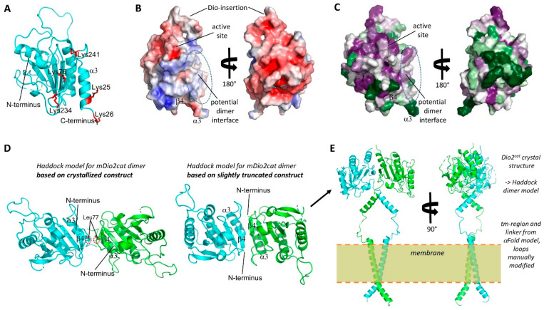
Figure 5.
Dio dimer architecture. (A) Crystal structure of mDio2 catalytic domain. The Lys residues identified through cross-linking MS to contribute to dimerization are shown in red and labeled. (B) Front and back view of the surface of the mDio2-cat crystal structure colored according to the electrostatic potential (calculated with APBS; red: negative potential, blue: positive). Key regions are indicated. (C) Front and back view of the surface of the mDio2-cat crystal structure colored according to sequence conservation (magenta: high conservation; green: low conservation). Key regions are indicated. (D) mDio2-cat dimers generated by Haddock based on the mDio2-cat crystal structure and cross-linking results. Using the complete crystal structure results in an anti-parallel dimer with a small interface formed by the N-terminal linker fragments sandwiched between the monomers’ β-sheet (left). Slightly truncating the N-terminal linker allows a similar association, but with improved interface through direct association of the sheets via β4. (E) Front and side view of a model for full-length mDio. The N-terminal trans-membrane helix and the linker were modeled with AlphaFold2, and the linker helix orientation manually adjusted to allow fusion to the N-termini to the optimized catalytic domain dimer (panel D, right).

