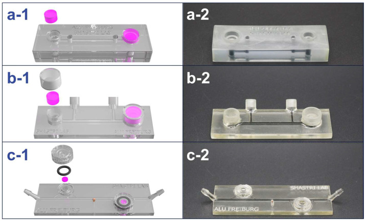
Figure 3.
Design evolution of the MiFD with digital renders and photos of selected iterations for better functionality. (a-1/a-2) First iteration and initial large concept. (b-1/b-2) Selected model from the intermediate stage of the design process. (c-1/c-2) Final design, optimized for interstitial flow at the modules with a sample port in the middle. The renders (a-1, b-1, and c-1) depict gel modules (pink), O-rings, and caps, with respect to each design. The channels in the photos (a-2, b-2, and c-2) were filled with an activated charcoal dispersion for better visibility.

