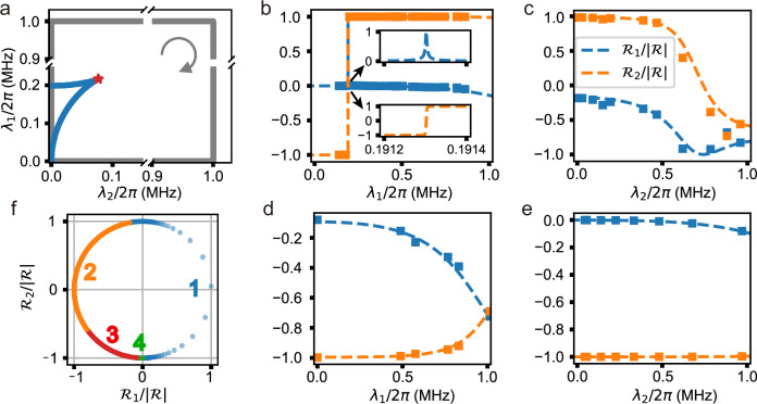
Fig. 3. Characterization of the NH topology.
a Loop traversed for extracting the winding number. The loop (gray solid line) is square-shaped with four vertices (0, 0), (λm, 0), (0, λm), and (λm, λm), where λm = 2π × 1 MHz. This loop surrounds an EP3 (red star), which connects two Fermi arcs consisting of EP2s (blue solid line). The arrow denotes the direction of the integral along the loop. b, e Normalized resultant vectors measured against λ1 with λ2 = 0 (b) and λm (d), and against λ2 with λ1 = λm (c) and 0 (e). The squares represent the components (blue) and (orange), respectively. The dotted lines denote the fitted and as functions of λ1 or λ2. The winding number, calculated with these fitted functions, is 1. f Trajectory of the rescaled unit resultant vector . The symbols “1'', “2'', “3'', and “4'', label the sections associated with the four edges of the parameter-space loop, shown in (b–e), respectively.

