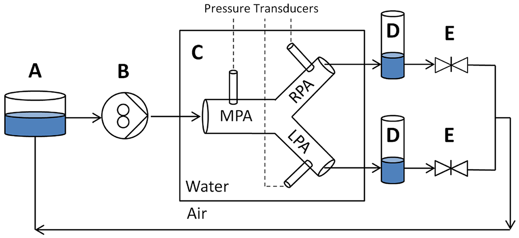
Fig. 1.

Schematic of the Mock Circulatory System experimental setup. Included components of reservoir A, pulsatile and MR-compatible pump B, patient-specific PA model with pressure transducers contained within water tank C, compliance chambers D, and right and left lung resistance gate valves E
