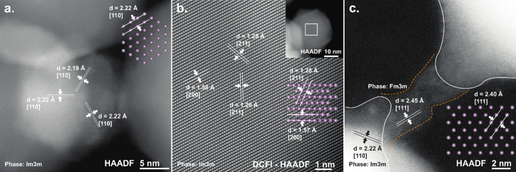
Figure 4.
a. HAADF (S)TEM image of a Mo NP where the [110] planes can be identified. b. Drift corrected frame integrated (DCFI)-HAADF (S)TEM image of a Mo NP (inset) where the [211] and [200] planes can be identified. c. (S)TEM image of two Mo-NPs where a filament has been formed between the two tips of the NPs due to biasing the device. The respective insets represent the Im3m body-centered cubic (bcc) crystal structures in their respective orientations. Although the filament crystal structure fails to match the bcc crystal structure of the NPs, it does match the Fm3m face-centered cubic, Mo crystal structure.

