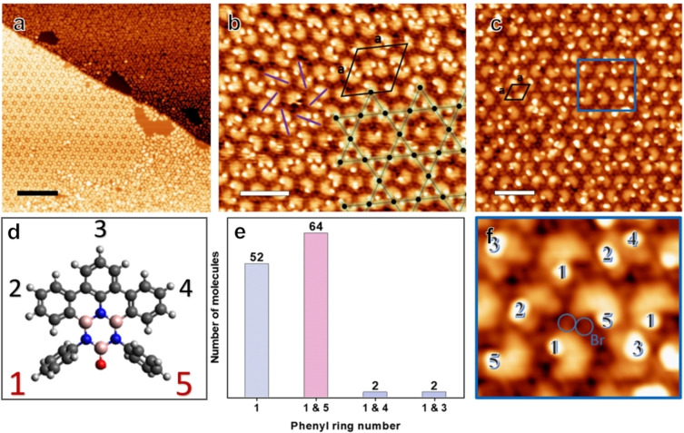
Figure 2.
(a) STM image of the coexisting self‐assemblies, i. e., the kagomé and hexagonal phase, observed after annealing at 170 °C. (b) STM image of the kagomé phase. The overlayed kagomé lattice points (black dots) are located at the centers of the dimers. The counter clockwise chirality of this domain is indicated by purple lines, the unit cell is represented by the black rhombus. (c) STM image of the hexagonal phase. (d) Molecular model with the numbering of the phenyl rings. (e) Histogram showing the statistics of the tilted phenyl rings of the dimers counted from the kagomé phase in (b). (f) Zoom‐in STM image of the area marked by a blue rectangle, highlighting the tilted phenyl rings (numbered accordingly) and showing the cleaved off Br atoms. (Image parameters (a) It: 0.16 nA, Vb: 1 V, scale bar: 20 nm, (b) It: 0.11 nA, Vb: 1.08 V, scale bar: 4.5 nm, (c) It: 0.13 nA, Vb: 0.82 V, scale bar: 4.1 nm.)

