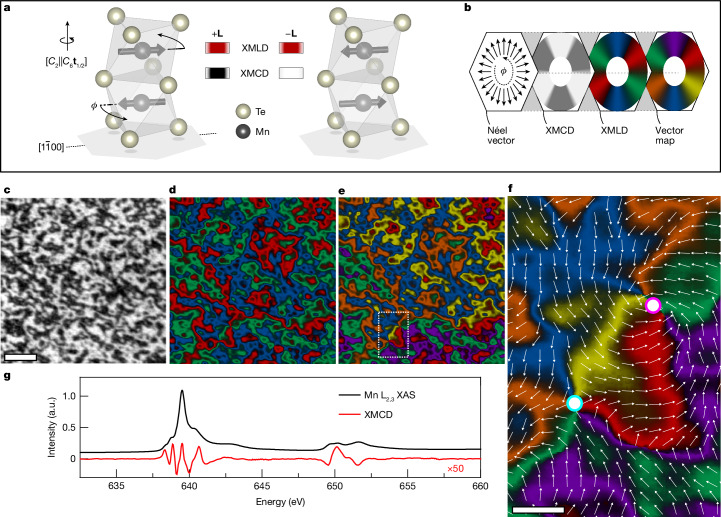
Fig. 1. Mapping of the altermagnetic order vector in MnTe.
a, Unit cell of α-MnTe with Mn spins collinear to the magnetic easy axis. Applying transforms the left unit cell into the right. The unit cells with opposite L vector produce the same XMLD but inequivalent XMCD owing to -symmetry breaking in altermagnetic MnTe. b, Illustration of the vector mapping process. The colour wheels show the angular dependence of the XMCD, three-colour XMLD and six-colour vector map on the in-plane L-vector direction. The XMCD acts on the three-colour XMLD, with light XMCD regions changing the colour and dark XMCD regions leaving it unchanged to produce the six-colour L-vector map. In the XMLD and vector map, coloured segments indicate the magnetic easy axes oriented along the crystallographic directions. c–e, XMCD-PEEM (c), XMLD-PEEM (d) and vector map (e) of a 25-μm2 region of unpatterned MnTe film. f, An expanded view of the boxed region in e in which a vortex–antivortex pair is identified. The vortex–antivortex core positions are highlighted by the magenta–white and cyan–white circles, respectively. The combination of XMLD-PEEM and XMCD-PEEM imaging allows for unambiguous determination of the helicity of the swirling textures of the altermagnetic order vector, indicated by the six colours and overlaid vector plot. Scale bars, 1 μm (c) and 250 nm (f). g, X-ray absorption spectrum (XAS), plotted in black, and XMCD spectrum, plotted in red, measured across the Mn L2,3 resonant edges. The XMCD spectrum is scaled by ×50. a.u., arbitrary units.

