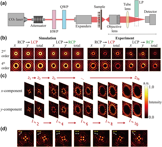
Figure 4:
Experimental setup and results. (a) Schematic diagram of the optical characterization setup. The numerical aperture of the objective lens is about 0.55. (b) Simulation and experiment diagram of the 2nd and 4th order of x-component, y-component, and total intensity on the x–y plane of LCP and RCP light incidence. (c) Transverse plane images of the x-component and y-component at each region at the x-LP light incidence. (d) Intensity distributions of the transverse plane of the x-component of the 2nd-order cylindrical vector field at the x-LP incidence. The yellow arrow represents the polarization direction of the incident LP light, while the white arrow represents the orientation of the linear polarizer. QWP: quarter-wave plate; HWP: half-wave plate.

