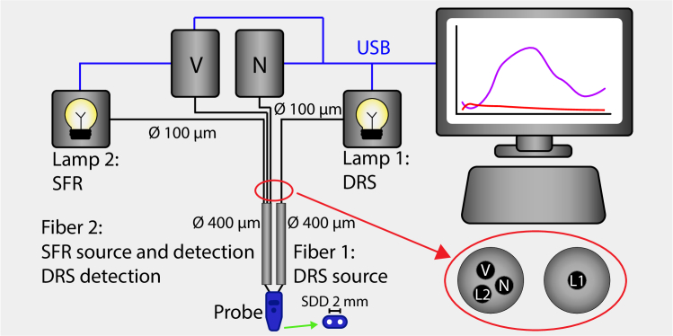
Fig. 1.
Overview of measurement setup. Two halogen light sources are used (Lamp 1 and Lamp 2) and two spectrometers (V, visible wavelength range, N, near-infrared wavelength range). For a DRS measurement, Lamp 1 is switched on. It is connected to Fiber 1 of the probe via a 100-micron fiber and leads the light to the tissue. At a 2 mm distance from Fiber 1, Fiber 2 collects light from the tissue and leads the light via two 100-micron fibers of the trifurcated fiber to the two spectrometers. For an SFR measurement, Lamp 2 is switched on. It is connected to Fiber 2 of the probe via the third 100-micron fiber of the trifurcated fiber. Again, Fiber 2 collects light from the tissue as well as the internal reflection and leads it to the spectrometers. The red-circled enlarged inset shows the connection between the 100-micron and 400-micron fibers. It uses two standard SMA fiberoptic connectors, connecting the 400-micron Fiber 1 to the 100-micron Lamp 1 fiber and the 400-micron Fiber 2 to the three sets of 100-micron fibers to Lamp 2 and the two spectrometers. This construction functions as a beam splitter with a very low (light source-to-detector) crosstalk. The green arrow points towards a schematic of the probe surface.

