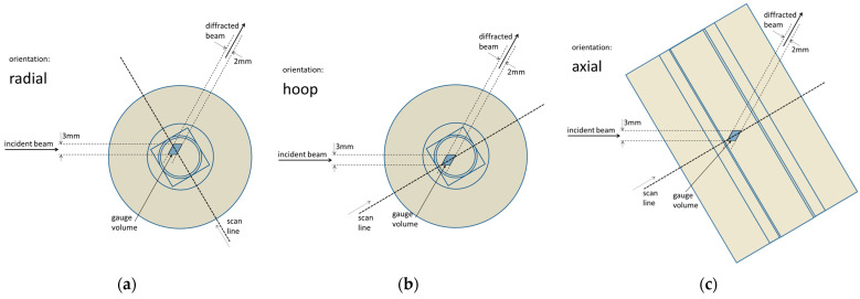
Figure 3.
Scheme of the scanned sample with the elements of the measurement geometry for all three scanned components of the strain: (a) radial = y-component, (b) hoop = x-component, and (c) axial = z-component. The contours inside and at the edge of the color areas indicate the edges of the imaginary cross-sections of the individual five samples used for the investigation (see Table 2 for sample dimensions).

