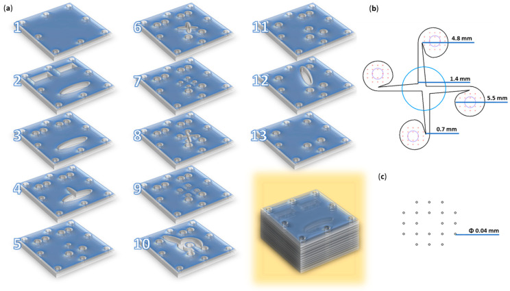
Figure 1.
Microfluidic platform configuration. (a) Schematic 3D representation of the microfluidic platform: individual layers and overlapped view. (b) Overlayed reaction area: blue—channel for iron precursors solution (layer 9); red—channels for salicylic–silica solutions (layer 9); black—vortex mixing chamber and its dimensions (layer 8); purple—collecting channels (layer 7). (c) Reactant inlet dimensions (layer 9). Adapted from our previous study [32].

