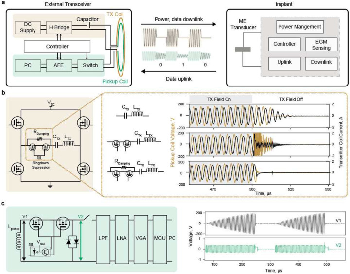
Fig.2|. ME backscatter external transceiver design.
a) Overview of the ME communication system components. The proposed system combines a custom external transceiver (Supplementary Fig1) and an mm-sized magnetoelectric implant. The power and downlink data are wirelessly delivered through the ME link; the ME backscatter is exploited for uplink communication. b) Transmitter ringdown suppression solution. The transmitter resonance circuit is powered by an H-bridge. To avoid cross-coupling between the transmitter excitation field and the backscattered field during the ringdown period, the transmitter ringdown is suppressed by adding an AC MOSFET in series to switch a 330-ohm damping resistor. c) ME backscattered field receiver circuit. The pickup coil is isolated from the detection circuit through a high-voltage AC switch during the excitation field. Once the field is off, the pickup coil is connected to the front-end detection circuit that combines a low pass filter(LPF), low noise amplifier (LNA), and variable gain amplifier (VGA) to amplify and filter the measured signal.

