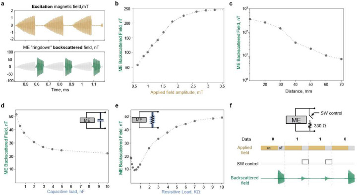
Fig.3|. Backscattered field characteristics.
a) Measured ME ringdown backscattered signal using the proposed external transceiver. The TX coil generates a pulsed magnetic field to excite the ME transducer. When the TX is turned off, the TX coil is silenced thanks to the ringdown suppression circuit. The RX coil detects the ME ringdown backscattered field. b) ME backscattered field as a function of the excitation magnetic field intensity. The amplitude of the excitation field was increased from 0.5 −3.5 mT while the frequency was fixed at 218kHz. The excitation field was superimposed on a 6.5mT DC field generated using a permanent magnet. c) ME backscattered field as a function of transducer-TRX distance. The ME transducer is placed at different distances from the center of the TRX coils. The excitation field at zero distance from the coil is set to 2 mT. In addition, a DC bias field of 6.5 mT was applied using a permanent magnet. d) ME backscattered field as a function of the capacitive load. Sweeping the capacitive load connected in parallel across the ME transducer changes the ME backscattered field. e) ME backscattered field as a function of the resistive load. Sweeping the resistive load connected in parallel across the ME transducer changes the ME backscattered field. f) ME load modulation induces backscattered field amplitude modulation. Switching the load across the ME transducer between an open circuit and 330-ohm load results in 0.6892 modulation depth of the backscattered field amplitude. Hence, to encode digital 0, the ME transducer is kept open-circuited; to encode digital 1, the transducer is connected to a 330-ohm resistive load.

