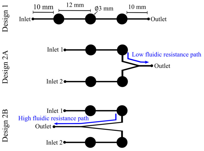
Figure 3.
Actuation channel design comparison. The lines represent the microfluidic channels, and the circles represent the actuation pads. Design 1 was the layout used for the single-channel actuation mode. For the two-channel design, two microfluidic layouts were tested—low-fluidic-resistance path design (2A) and high-fluidic-resistance path design (2B).

