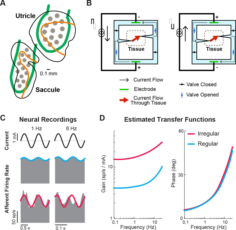
Figure 11. Ongoing developments toward more naturalistic stimulation in vestibular prostheses.
(A) Schematic of the electrode array for stimulation of the otolith organs. Gray circles denote electrode contacts. Orange lines denote the line of polarity reversal (i.e. where different hair cells are sensitive to different motion directions). Adapted from Figure 1 from Hageman et al., 2020. (B) Schematic of a safe direct current stimulator, which can continuously deliver direct current in one direction to tissue while preventing unwanted electro-chemical reactions at the electrode interface. Adapted from Figure 1 from Aplin and Fridman, 2019. (C) Firing rate of recorded canal afferents in response to galvanic vestibular stimulation (GVS). (D) Estimated transfer functions of the afferent response to GVS from the neural data in (C). Panels C and D have been adapted from Figure 2 from Kwan et al., 2019.

