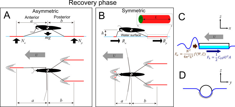
Figure 3.
Graphical explanation of the basic concepts in the model of sliding water strider. (A,B) schematics of asymmetric (A) and symmetric (B) sliding, and variables used in the model: anterior and posterior normal forces (, ), the anterior and posterior resistance forces (, ), wetted leg lengths () and diameters (), horizontal distance along line parallel to the moving direction from the centre of the mass to the centre of the anterior and posterior supporting wetted legs (,), body height above water surface (), body velocity (). (C,D) the two main forces contributing to the total resistance: hydrodynamic drag (; brown) and wave drag (; blue). The light blue area (C) and dotted line (D) represent the wetted area of a sliding leg. is the surface tension coefficient, is the density of water, is the relative velocity of the water strider to the water and is the wetted area of the leg. The wave drag, , is induced by the wave generated by the cylindrical leg as shown in C. is the normal force on the leg from the water (A), is the leg length, is the shape of wetted area depending on the shape of the leg and its moving direction. is designed to simplify the formula. See details in electronic supplementary material 1, parts 3 and 4 (electronic supplementary material, figures S13–S27).

