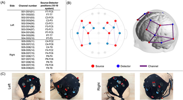
FIGURE 1.

(A) 10–10 Locations of source‐detector pairs. (B) 2D and 3D views of the montage used. Sources are shown in red, detectors are shown in blue, and channels between them are shown in purple. (C) A model of a newborn wearing an fNIRS cap setup with our montage.
