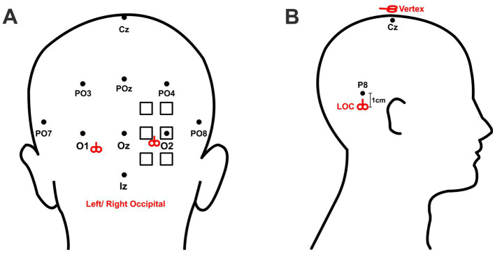
Figure 1.
Localization of stimulation sites. The standardized 10–10 EEG coordinate system was used for localizing stimulation targets. (A) The six possible stimulation sites for right occipital stimulation are marked by the squares. The final stimulation site was defined by the location which elicited the strongest phosphene. For left occipital stimulation, corresponding regions on the left hemisphere were stimulated. The coil handle pointed upward for occipital stimulation. The right and left mean locations of occipital stimulation are marked by the red symbols of coil. (B) LOC stimulation was applied 1 cm below position P8 (for left LOC) or P7 (for right LOC). Control stimulation was applied over the vertex, defined as position Cz. The coil handle pointed upward for LOC stimulation and posteriorly for Cz stimulation.

