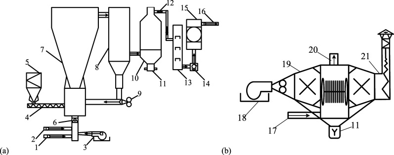
Figure 1.
Schematic of the bench-scale circulating fluidized bed (CFB) gasification producer (a) and the catalytic reforming reactor (b). (1: Steam inlet channel, 2: oxygen inlet channel, 3: air blower, 4: screw feeder, 5: biomass bin, 6: main airflow intake, 7: gasifier, 8: cyclone separator, 9: return feeder, 10: catalytic reformer, 11: tar sampling port, 12: gas sampling port, 13: spray tower, 14: Roots blower, 15: syngas tank, 16: syngas outlet, 17: crude gas inlet, 18: burner, 19: reformer, 20: connect the spray tower, 21: chimney.)

