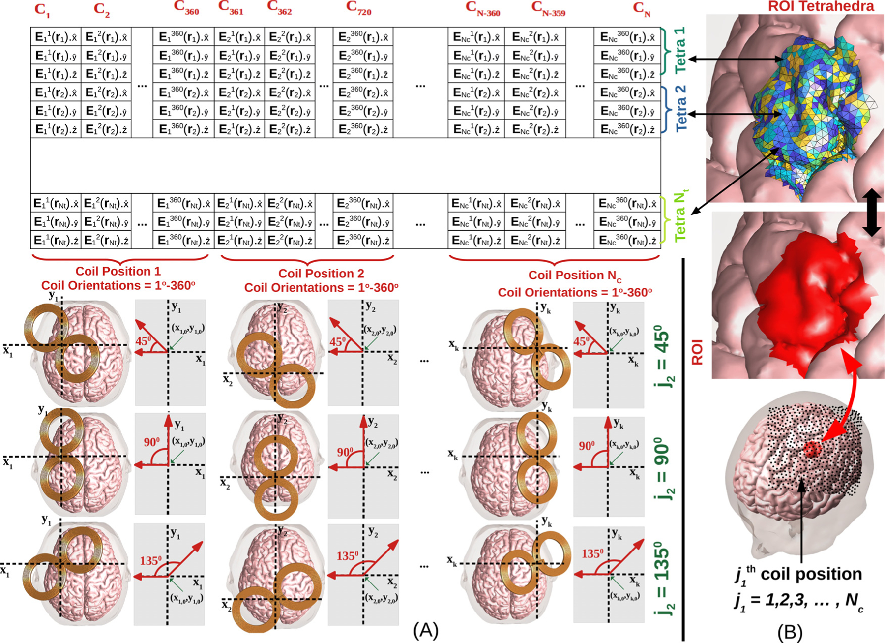
Fig. 1.

(A) The coil placement to E-field mapping table contains E-fields in the ROI for all coil placements, where Nt is the number of tetrahedra in ROI, Nc is the number of coil positions, and N is the number of coil placements (N = 360Nc). Each column of the table is the induced E-field in every ROI tetrahedron for a fixed coil placement. Each row of the table denotes the E-field induced in a fixed tetrahedron for all possible coil placements. For each coil placement, orientations are defined by rotating the coil tangent to the scalp and about its center as shown. Here a local coordinate axis tangential to the scalp and centered about the coil is defined by setting the unit vector pointing posterior to anterior. The angles are defined as the polar angle on this coordinate system. Example coil orientations corresponding to j2 = 45° , 90° , and 135° are shown for several coil positions. (B) TMS coil positions are denoted by black dots over the scalp of the head model and are typically chosen on a large region covering the ROI (red region).
