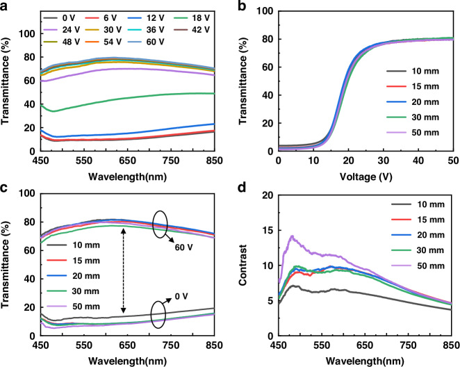
Fig. 3. The test distance and broadband evaluation of PDLC devices indicting high switch ratio performance.
a With the increase of the applied voltage, the transmittance change diagram of PDLC device (thickness = 13 μm) in visible wavelength range shows that when voltage < 12 V, the transmittance is lower than 20%, while voltage > 24 V, it has a transmittance higher than 60%. b The voltage-dependent transmittance of PDLC of variations at different test distances between detector and PDLC. c Transmittance of PDLC under different test distances (10 mm ~ 50 mm) at various wavelengths (450 nm ~ 850 nm) without voltage application (0 V) and with saturated voltage (60 V), showing high contrast across entire visible spectrum. d Contrast of PDLC device under different test distances at various wavelengths without voltage application and with saturated voltage

