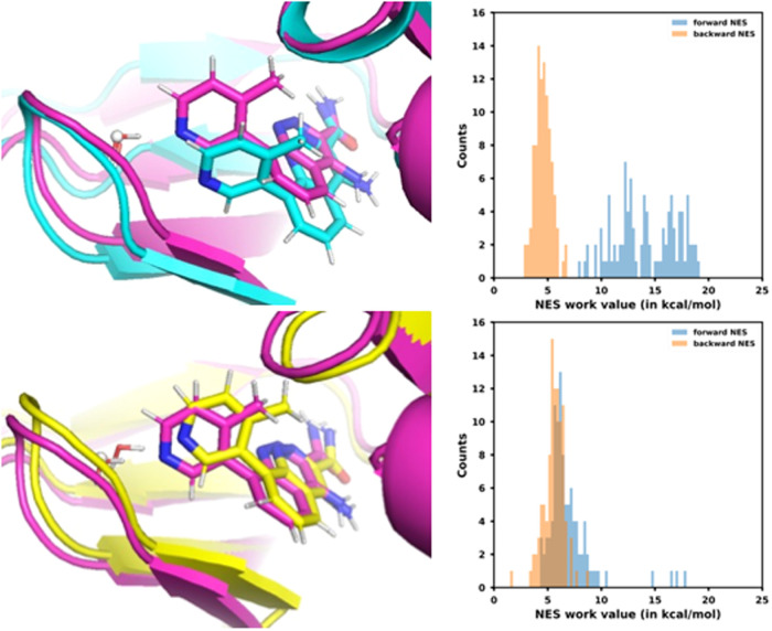
Figure 8.
Comparison of the binding poses of the ligand S8 in two replicates of the BTK simulations for the state where the harmonic restraint on trapped water, solvent repulsion, and the position restraints on the binding site are in place (stage 5, Figure 4). On the left, two different poses for the ligand S8 are shown, and on the right, the corresponding NES work distributions plots for ligand transformation in the two replicates are shown. (Left) In the upper and lower images, the magenta pose corresponds to the ligand’s true binding pose in an equilibrated starting structure used for the simulations and is shown as the reference. The binding poses in yellow and cyan correspond to the binding poses in the two simulation replicates. The trapped water is shown in sticks and the restraint site of the trapped water is shown in gray spheres. In the cyan binding pose of the ligand, the ligand has unidirectionally translated away from its binding pose in the equilibrated starting structure of the simulation, which yields no overlap in the NES work distributions. In the yellow binding pose of the ligand, the ligand does not translate too far from its position in the equilibrated starting structure and yields a converged binding free energy calculation.

