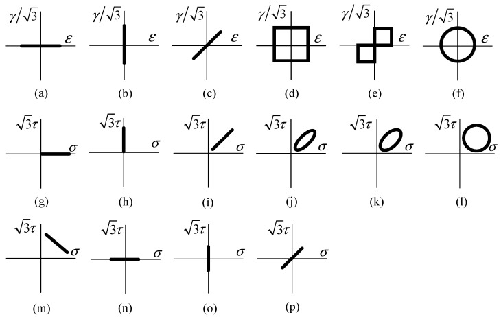
Figure 1.
Loading paths. (a,n) are axial loading; (b,o) are torsional loading; (c,p) are proportional loading. For of them, φ = 0°; (d–f) are non-proportional loading, φ = 90° in paths (d,f), φ = 45° in path (e); (g) is axial loading with not-zero mean normal stress; (h) is torsional loading with non-zero mean shear stress; (i) is proportional loading with non-zero mean normal and shear stresses, φ = 0°; (j–m) are non-proportional loading with non-zero mean normal and shear stresses. φ is 30°, 45°, 90° and 180° respectively. Among them, (a–f) are strain controlled loading, (g–p) are stress controlled loading.

