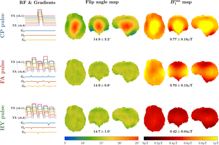
FIGURE 2.

Left column: transmit radiofrequency amplitude and gradients for the considered pulse types (top row: circular polarized (CP) mode pulse; middle row: flip angle optimized kT‐points pulse; bottom row: hybrid [HY] optimized kT‐points pulse). Their resulting flip angle and maps are shown in the middle and right columns, respectively, with the average ± SD of each property depicted below. Target flip angle 15° in all cases, target μT for the HY pulse (λ = 0.5).
