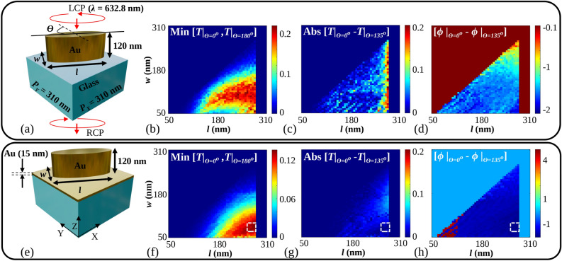
Figure 2.
(a) Cross section of the MoS unit cell, (b) minimum value between the transmittivities, T for  and
and  for MoS unit cell, (c) difference between the transmittivities, T at
  and
and  for MoS unit cell, (d) difference between the phase,
  for
for  and
and  for MoS unit cell, (e) proposed cross section of a unit cell composed of Metallic elliptical nanoparticle over metal (MoM) sheet on a glass substrate, (f) minimum value between the transmittivity, T for
  and
and  for the MoM unit cell, (g) difference between the transmittivities, T at
  and
and  for the MoM unit cell, (h) difference between the phase,
  for
for  and
and  for the MoM unit cell.
  is the orientation angle of the major axis of the elliptical nanoparticle with respect to the Y axis. Input is taken as Left Circularly Polarized (LCP) light, and output is taken as Right Circularly Polarized (RCP) light. ‘Min’ and ‘Abs’ are abbreviated for minimum and absolute values.

