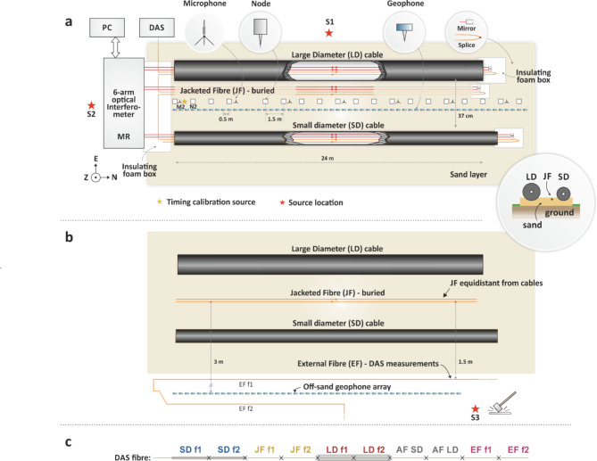
Fig. 2.
(a) Schematic of the measurement setup (not to scale). Optical fibres interrogated by the 6-arm interferometer are coloured red; Fibres used for DAS measurements are coloured orange and are spliced together forming a single optical path. MR: measurement rack; PC: computer used for the acquisition of interferometer and microphone data; S1, S2 and S3: source locations; (b) Illustration of the setup used for investigating the fast wave phenomenon. JF was rearranged equidistantly from the LD and SD cables, and an additional DAS fibre section (EF) and a geophone array were installed off-sand. (c) Illustration of the different sections of the fibre interrogated by the DAS system. Crosses indicate the splice points. AF refers to fibre attached directly to the armour, which is discussed later.

