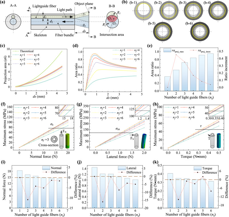
Fig. 2. Design and characteristics of the probe.
a Schematic of light path transmission through the probe embedded with a central fiber bundle (labeled in light blue) and a light guide fiber (labeled in light green). A-A sectional view shows the geometrical layout and B-B sectional view shows the light covering status on the object plane, where the intersection area (labeled in light red) denotes the effective imaging region. b The theoretical projection area on the object plane at 4.5 mm when using different numbers of light guide fibers. The outer gray and the inner white area denote the theoretical imaging region and the effective imaging region, respectively. c The projection area variation against distance using different numbers of fibers. d The ratio of the effective imaging zone over the theoretical imaging zone against distance. e The analytical comparison of the maximum area ratio with different numbers of light guide fibers, which suggests that the effective image area increase is not significant after the number of fibers is more than three. The finite element analysis (FEA) results of the skeletons with different hollow structures under normal force (f), lateral force (g), and torque load (h). The insets in the corner are the FEA simulation results of the skeleton with four peripheral holes. The analytical comparison of the mechanical strength of the skeletons with different hollow structures when reaching the normal (i), lateral (j), and torsional (k) stress limit. After considering the balance between imaging, strength, and function, we finally developed the skeleton structure with a central lumen for fiber bundle, three uniformly circumferential arranged holes for light guide fibers and another hole for functional tools. Source data are provided as a Source Data file.

