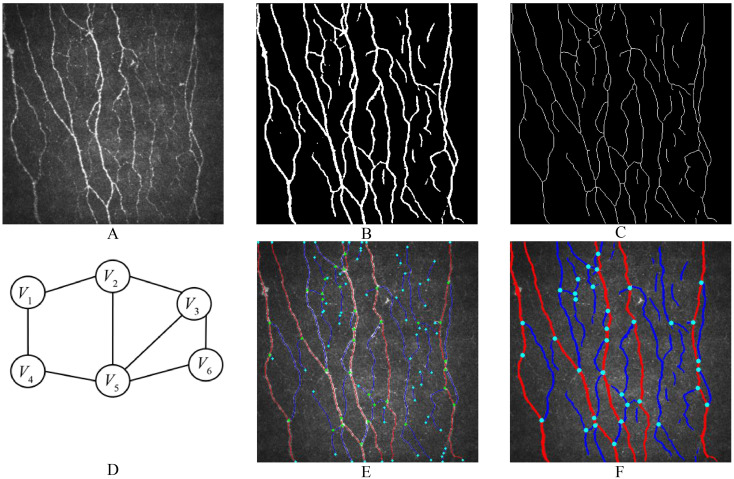
Figure 2.
Workflow of image processing. (a) is the original image, which is segmented by the DL model to obtain the binary image (b). Afterward, image thinning and skeleton extraction algorithms are applied, resulting in the CNF skeleton image (c). (d) illustrates the construction of an undirected graph from each CNF segment and branching point for trunk or branch determination. (e) and (f) respectively depict images showing the skeleton of the CNF or the entire processed result.

