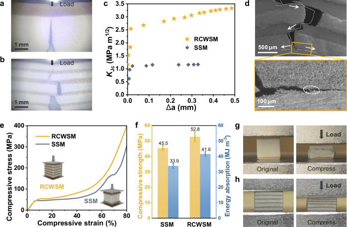
Fig. 3. Fracture modes and failure behaviors of the RCWSM.
a, b Optical micrographs of sandwich structural material (SSM) (a) and RCWSM (b) taken from in situ single-edge notched bend tests. c Rising crack-extension resistance curves (evaluated by the steady-state fracture toughness KJc) of the SSM and RCWSM. d SEM images of the crack propagation behavior of the RCWSM in the single-edge notched bend test. The area magnified in the orange box is the crack branch, and the white dotted oval box marks the crack bridge. e Compressive stress-strain curves of the SSM and RCWSM. Insets: compressive stress direction of the RCWSM (left) and SSM (right). f Compressive strength and energy absorption of the SSM and RCWSM. Error bars show standard deviation with at least four repeats. g, h Photographs of the SSM (g) and RCWSM (h) before and after the compression test.

