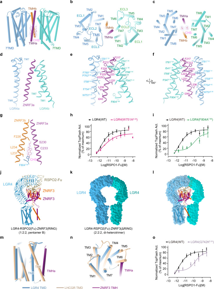
Fig. 4. LGR4 induces ZNRF3 into an inactive state.
The transmembrane interface between LGR4 and ZNRF3 in the LGR4-RSPO2-ZNRF3(ΔRING) complex (2:2:2, di-heterotrimer) is shown from the front view (a), top view (b) and bottom view (c). d The interface between the transmembrane domains of LGR4 and ZNRF3. e, f The side chain interactions between LGR4 and ZNRF3 within the transmembrane region of the LGR4-RSPO2(Fu)-ZNRF3(ΔRING) complex (2:2:2) are shown in detail. g The specific interactions between the transmembrane domain of LGR4, ZNRF3 and cholesteryl hemisuccinate within the LGR4-RSPO2(Fu)-ZNRF3(ΔRING) complex (2:2:2) are highlighted. h, i Dose-dependent TOPFlash activity induced by WT (black) or W751A6.39 mutant (red, e) and F804A7.56 mutant (green, f) of LGR4 after stimulation with RSPO1, n = 3. Source data are provided as a Source Data file. j–l Comparing the LGR4 in pentamer B and di-heterotrimer. j The model of LGR4-RSPO2ZNRF3(RING) (1:2:2, pentamer B). k The surface of two LGR4 in LGR4-RSPO2ZNRF3(ΔRING) (2:2:2, di-heterotrimer). l Superposition of the LGR4 in pentamer B and di-heterotrimer (ZNRF3 and RSPO2 are deleted for clarity). m, n Conformational comparison of the TMD of LGR4 (light blue) in the di-heterotrimer with that of active LHCGR (wheat, PDB:7FII, RMSD = 1.524, 182 to 182 atoms) from the front view (m), and bottom view (n). The potential steric clash between TM6 of the active LGR4 and the single TM helix (violet) of ZNRF3 in the di-heterotrimer complex is shown. o TOPFlash plot illustrating the effect of breaking ionic lock (Q742K6.30 mutant) (purple) in the transmembrane domain of LGR4 on the activity of RSPO1, compared to that of WT (black), n = 4. Source data are provided as a Source Data file. Each value represents the mean ± SEM from independent experiments. The LGR4(WT) datasets in all three panels are identical.

