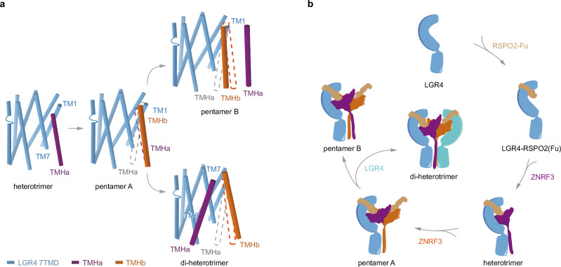
Fig. 6. Proposed model for the LGR4-RSPO2-ZNRF3 complex assembly pathway.
a Front view of the transmembrane region of the LGR4-RSPO2-ZNRF3 in the different states aligned by the LGR4 TMD. The dashed line (violet/orange) indicates the position of ZNRF3 TM helices in the previous state. TM helix(a) is not visible in pentamer A, and the dashed line is colored in gray. For clarity, one LGR4 is omitted from the di-heterotrimer. b Cartoon illustrates the assembly pathway from the LGR4-apo state, and RSPO2-bound state, through LGR4-RSPO2-ZNRF3 (1:1:1, heterotrimer) state to LGR4-RSPO2-ZNRF3 (1:2:2, pentamer A) state, and then differentiates into the LGR4-RSPO2-ZNRF3 (1:2:2, pentamer B) state in the absence of LGR4, or into the LGR4-RSPO2-ZNRF3 (2:2:2, di-heterotrimer) state in the presence of LGR4.

