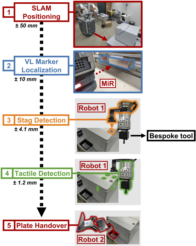
FIGURE 2.
Flow diagram detailing the robot–instrument interaction, highlighting the steps in sequence. SIMO uses SLAM to move to the waypoint, defined for every experimental station (1), and then it localizes the VL Marker, associated with the station (2). uses computer vision to estimate the marker’s pose (3), and then it exploits impedance control and the specialized tool to touch the instrument on three faces (six-point touch feedback) (4). can perform plate placement after it is informed by about the instrument’s pose (5).

